Announcement

Collapse
No announcement yet.

Newb with 5e3 problems

Collapse
X
 
  • Filter
  • Time
  • Show
Clear All
new posts

  • Newb with 5e3 problems

    Howdy all. New to the forum...this is my second build (built a lite IIb a while back).

    Anyways. Amp is built, wiring has been double checked--although I'm a little foggy on a couple spots. Amp fires up, tubes light. Voltage at the first big cap is 416, cathode voltage is 22--all acceptable. I'm getting no noise at all out of the speaker jack. I was wondering if there's a few more spots on the board I could poke around with a multi-meter to see if I could isolate the problem.

    I get the notion of high voltage, etc. Will be careful...Also, as strange as this sounds, I haven't had to drain the caps yet. Not sure if this is part of the problem...

    Thanks in advance.

  • #2
    Hey ES347 -- I just built my first 5E3 (actually, my first amp build of any kind). Isn't it exciting?

    Is your speaker jack grounded?
    What grounding scheme did you use?

    Do you have any pics of the inside of your build?

    BTW, I own an ES347. It sounds great in a 5E3.

    Comment


    • #3
      It's funny you should ask about the speaker jacks...It doesn't seem to be grounded to me. The OT secondary goes to the tip (jumpered to the tip on the second out) and the ring and sleeve are jumpered. This was one of two spots in the instructions that were a bit foggy for me...the other was the wiring of the input jacks.

      I'll snap some pics in a few...

      Comment


      • #4
        Pics

        Couple came out blurry, but anyways--

        Pictures by ES347 - Photobucket

        Comment


        • #5
          Originally posted by ES347 View Post
          It's funny you should ask about the speaker jacks...It doesn't seem to be grounded to me. The OT secondary goes to the tip (jumpered to the tip on the second out) and the ring and sleeve are jumpered. This was one of two spots in the instructions that were a bit foggy for me...the other was the wiring of the input jacks.

          I'll snap some pics in a few...
          Did you hook up both secondary wires from the OT, one to the output jack tips, the other to the output jack rings? The pic was a little fuzzy for me to tell...

          I can't see where your grounds go. Do they come from underneath the eyelet board and come to a star somewhere with the black wires? Where does the ground from the first triode's cathode cap/resistor go, for example? I don't see the wire coming from the ground point of the cathode cap/resistor, but maybe it's hidden by the eyelet board (?).

          Comment


          • #6
            My OT only had one secondary, which has been confusing for me. As far as I can tell, unless the speaker outs are grounded due to the fact that the jacks are connected to the chassis, they aren't currently grounded. Which part of the jack gets grounded...Currently, the secondary goes into the tip of the first jack (which is jumped to the tip of the second jack). The sleeve and ring on the first jack are jumpered together, but don't go anywhere. No wire is connected to the sleeve on the second jack, and this one is a mono jack so there is no ring.

            As far as the rest of the grounding goes, it's all underneath the board and is according to the old Fender diagram, meaning it's four spots off the board and two spots off the guitar inputs (along with the PT, etc.). This stuff is all grounded to the upper right post of the PT. If you look carefully at the pics, you'll see all the wires running along the tone/volume side of the board, kinda tucked in.

            Comment


            • #7
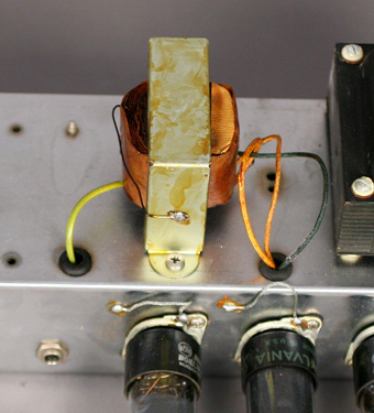
              The OT has to have a "return" somewhere that goes to ground. The old layout only shows one wire because the other wire was soldered directly to the OT casing, which is then grounded to the chassis by virtue of it being screwed to it. As below:


              What kind of OT do you have? There should be a second ("return") output wire somewhere. I suppose it's possible it's connected to the casing internally. In which case, if you take a continuity tester (or ohmmeter) and measure from the one output lead you have to the casing or, better, to the amp chassis you should get a "beep" or a very low resistance reading.

              The type of output jacks you have look like their "rings" should already be grounded to the chassis by being bolted to it.
              Last edited by mbratch; 05-03-2009, 02:53 AM.

              Comment


              • #8
                Mine is like the one in the picture...the one I bought is Mercury Magnetics. So I guess it's already grounded.

                Found a wire that was messed up underneath the board. Going to test it in a few.

                Comment


                • #9
                  Man...so now I have a new problem. I'm finally getting a sound, but it's just a buzzing sound. Is there any way to check an OT with a multimeter? Wondering if I torched it in the process.

                  Comment


                  • #10
                    Originally posted by ES347 View Post
                    Man...so now I have a new problem. I'm finally getting a sound, but it's just a buzzing sound. Is there any way to check an OT with a multimeter? Wondering if I torched it in the process.
                    A couple of questions:
                    • Do you have a 100 ohm resistor coming from each terminal of the pilot lamp to ground (not in the original Fender drawing)?
                    • Where does that blue/purple striped wire from the PT lead to? In your pics, it seems to go nowhere.

                    If the PT has both a 5v center tap and a high-voltage center tap, both need to go to ground. If it does not have the HV center tap, then you need the resistors.

                    Comment


                    • #11
                      I do have the two resistors going to ground, so I think the blue wire should be fine. I'll trim it and tuck it when I get this thing working. One piece of info that should help isolate my problem is that the volume & tone knobs effect the hum. Volume makes it louder, tone changes the tone. Does this narrow any thing down?

                      Comment


                      • #12
                        There could be a couple of possible causes of the noise.

                        However, what sticks out to me right now is that you have all your grounds starred to the same location. If you do a forum search here on "grounding" you'll find that grounding systems tend to separate the power section grounding from the pre-amp section. Even the vintage Fender amps layout that you're attempting to model used a brass plate for the pre-amp and PI grounds, and the PT CTs and AC ground coming in were grounded to the chassis near the PT.

                        Comment


                        • #13
                          So am I creating a ground loop by doing it this way?

                          Comment


                          • #14
                            I recommend some reading.

                            Comment

                            Working...
                            X