Announcement

Collapse
No announcement yet.

5e3 build problem

Collapse
X
 
  • Filter
  • Time
  • Show
Clear All
new posts

  • 5e3 build problem

    Hi all,

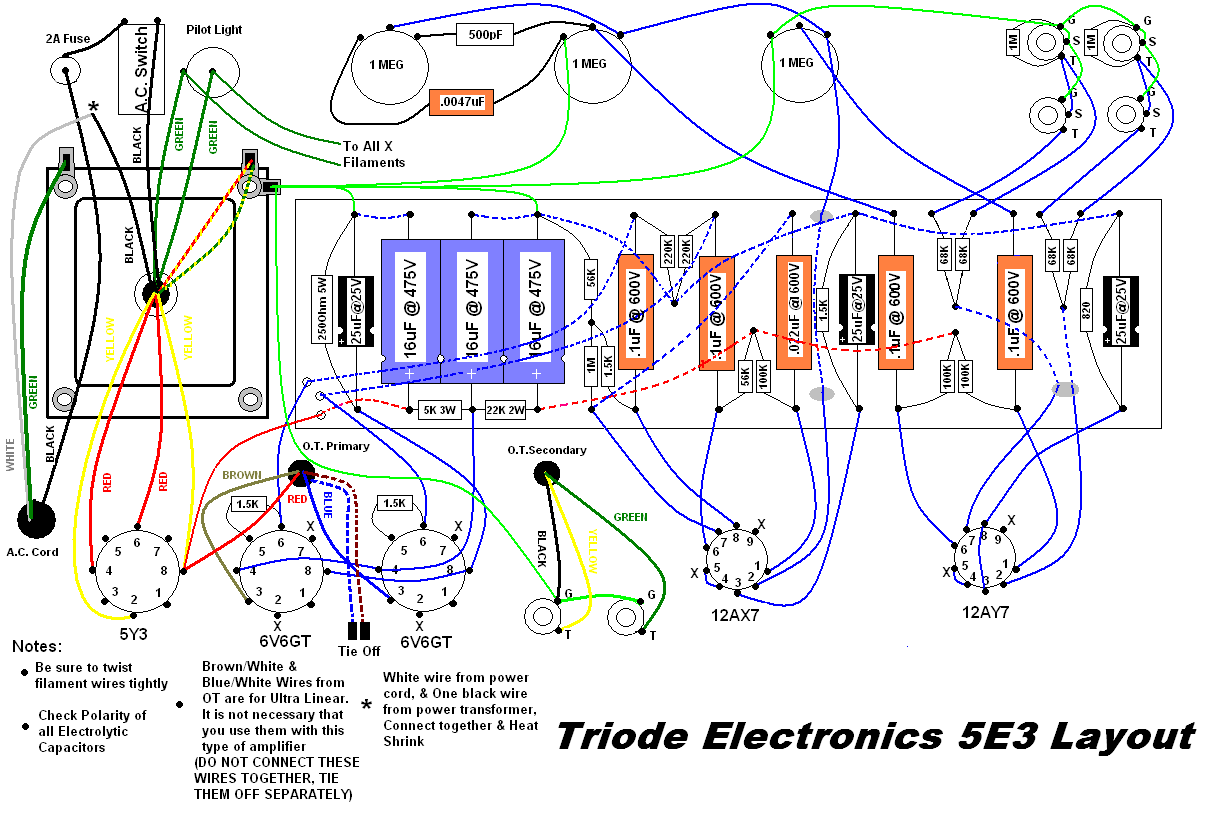
    finally my finished my 5e3 kit (from triode electronics but with an extra carling switched wired in using the the ceriatone 5e3 diagram), my first build, tried to power it up for the first time (was so excited to get proper tweed tone as i've never owned any tube amp before), into an 8 ohms celestion vintage 30, all tubes appeared to heat up nicely with an orange glow, and as soon i flipped the standby switch a loud hum came through the speaker. I plugged my guitar into each input to see whether it was background noise or not, but there was no sound from the guitar at all; just loud, uninterrupted humming. Ive checked all my wiring so many times now and cannot find anything wrong.

    Here is the wiring diagram i was given for the primary transformer, I live in england so I needed to wire it for a 240V input.

    The best I could understand the instructions at the bottom was to feed the live 240v into the white, and the neutral to the black/white, and then join the white/black and black wires. Bit I'm still unsure, so i think there's this could be the problem. Emailed triode to get some help but its been a week and a half and still no response.

    some pics:


    Singed the the plastic coating of the large capacitors a little as I soldered my circuit board, will this affect anything?

    I'm armed with a multimeter but not sure what size voltages are supposed to be read from where as triode only gave me the diagram above and a wiring diagram. If anyone could give us a clue as to what to do, it would be greatly appreciated.

    thanks in advance, tris

    p.s. sorry for the essay, thought i better give as much detail as possible.

  • #2
    Look at post #14 in this thread:

    http://music-electronics-forum.com/t12667/

    The tube referenced is the one on the right in your pictures and the grid pin is 2 or 7.

    The diagram for the transformer shows two 100 ohm resistors to ground from the green wires but I don't see these anywhere in your pictures. They are needed to reduce or eliminate hum. Most people solder them to the pilot light, twist the free ends together and run a wire to ground.
    WARNING! Musical Instrument amplifiers contain lethal voltages and can retain them even when unplugged. Refer service to qualified personnel.
    REMEMBER: Everybody knows that smokin' ain't allowed in school !

    Comment


    • #3
      Check solder joint on 1m resistor...

      Look at the 1M 2 watt CC between the 3rd filter cap and 1st phase inverter cap.) The lower jount looks like it is not soldered well. Also, is it connected to pin 6 of V2? It looks like it might be connected from the bottom with a brown wire.

      Good luck.
      Mandopicker

      Comment


      • #4
        cheers loudthud, just did your recommended check and all my readings correspond with yours im afraid so i guess thats not the problem, thanks for your time though

        Comment


        • #5
          Originally posted by classyelf View Post
          cheers loudthud, just did your recommended check and all my readings correspond with yours im afraid so i guess thats not the problem, thanks for your time though
          loudthud was saying that you appear (from your pics) to have omitted the pair of 100 Ohm artificial-ground-reference resistors on your heater circuit. I can't see them either. (In situations where your PT heater winding doesn't have a centre tap, you need another way to ground-reference the heater circuit - this is what the 100R resistors are for)

          As for the mains wiring:

          the 'phase' (or 'active') mains wire goes to the bottom of the fuse holder first, then the top of the fuse holder to the mains switch, and thence to the corresponding side of the PT primary. The 'neutral' mains wire goes straight to the other side of the PT primary. The mains 'earth' wire bolts securely straight to the amp chassis. I would put a proper mains socket on your chassis. Having the mains cord taped up like that is risky and dangerous. I would also get some rubber grommets from an electronics store to fit into the holes in your chassis where the wires pass through (to protect the wire insulation)

          I am not sure what your other switch is doing there - there appear to be a couple of wires going out the back of the chassis (Are these going to the OT) Can you supply a schematic and rear shot of your chassis?

          You also might benefit from tidying up your wire layout. Its a bit higgledy piggledy. Bad wiring can contribute to hum. As a rule, keep your all your AC pairs twisted together (including the HT secondaries off the PT and the primaries and secondaries off your OT). Keep all DC wires and signal wires away as far as possible from AC wires, and where necessary, only cross them at right angles, otherwise you can induce hum from the AC EMF into the DC wires. Keep your wires as short as possible. Long wires contribute to hum. If they have to be long, lay them right up against teh chassis. This helps 'eat-up' stray EMF around the wire

          You might benefit from shielding your input cable from your input sockets to both grids of V1, as well as the signal wire from the vol pot to the grid of V2. Use shielded cable and ground each cable shield at one end only. You will have to put the 68k input resistors right on the input sockets if you are going to do this effectively.
          Last edited by tubeswell; 06-04-2009, 05:06 PM.
          Building a better world (one tube amp at a time)

          "I have never had to invoke a formula to fight oscillation in a guitar amp."- Enzo

          Comment


          • #6
            sorry mandopicker I'm a complete novice to amp building so I didnt understand half of that lol, but if your talking about the rather fat 1meg resistor in between the blue and orange capacitors - it's soldered on the under-side of the turret to the brown wire that leads to pin7 of the left preamp tube and i just checked it for continuity and its fine. Was that what you were talking about?

            Comment


            • #7
              Is the red/blue wire gounded? It should be left unconnected. The red/yellow wire looks like it is grounded and that is correct.
              WARNING! Musical Instrument amplifiers contain lethal voltages and can retain them even when unplugged. Refer service to qualified personnel.
              REMEMBER: Everybody knows that smokin' ain't allowed in school !

              Comment


              • #8
                cheers loud thud, i'll disconnect and heat shrink the red/blue wire form ground. I've been searching the the whole house high and low for a pair of 100 ohm resistors as triode did not include a pair. The closest i found was a 115 ohm and a pair of 50 ohm resistors. I know its not the proper way but i'm dying to get this working - would using the two 50 ohm reisistors in series and the 115 to ground the green wires work? thanks for everyones help so far

                Comment


                • #9
                  Originally posted by classyelf View Post
                  would using the two 50 ohm reisistors in series and the 115 to ground the green wires work?
                  Not very well

                  The idea of the 100R resistors on each side is to use 1% tolerant resistors so that you get the same amount of ground reference on each side of the heater winding (which you need to eliminate the hum from the heater circuit)/ If you have different value resistors on each side of the winding, the VAC swing will be unevenly distributed between the heater wires, which will make for hum.
                  Building a better world (one tube amp at a time)

                  "I have never had to invoke a formula to fight oscillation in a guitar amp."- Enzo

                  Comment


                  • #10
                    thanx tubeswell, I will do some tidying up and get myself a pair of accurate 100 ohm resistors.

                    The problem with my transformer wires is that I have no clue which transformer wire is supposed to be the phase, neutral or earth wire as this was all that triode gave me:


                    The red wire from my other switch does go to my OT, I wired it according to ceriatone's diagram:


                    as I wanted a standby switch. It appeared to work when I fired up the amp as the switching of it would turn the hum (the only noise I could get out of it) on and off.

                    Also I will be tidying up the holes and replace the mains cable with a kettle lead socket like on marshall amps. The taped up cable was a temporary measure just to get the amp working first, thanks for your concern though.

                    I'll let you all know how it goes when I get these 100 ohm resistors in place, tris

                    Comment


                    • #11
                      On their layout diagram the wire going to the "0" on the Pt is neutral. The wire going to either one of the 120, 220, 240V terminals is the phase wire.
                      Building a better world (one tube amp at a time)

                      "I have never had to invoke a formula to fight oscillation in a guitar amp."- Enzo

                      Comment


                      • #12
                        That's right...good check...leave no stone unturned.
                        Mandopicker

                        Comment


                        • #13
                          Any heater ground ref is better than none. The 5E3 schematic shows one side of the heater grounded. That will be easy to do and should get rid of the vast majority of the hum. If you make the ground connection via a 50 ohm resistor, it will provide some protection for the transformer in case a tube develops an internal short.
                          Or instead of connecting it to ground, connect it to the power tube cathodes. That will elevate the heaters to 25v above ground and so act to minimise hum. Peter.
                          My band:- http://www.youtube.com/user/RedwingBand

                          Comment


                          • #14
                            I hoping grounding that red/blue wire didn't damage your transformer. Carefully measure the AC voltage at pins 4 and 6 of the rectifier tube. Expect about 300 to 350V AC on each pin to ground. Connect one lead from the DVM to the chassis with a clip lead or stick the probe in a hole so you don't have to touch that probe and, with one hand behind your back, touch the other probe to the pin at the socket. Be extra carefull not to touch any part of the amp while doing this.
                            WARNING! Musical Instrument amplifiers contain lethal voltages and can retain them even when unplugged. Refer service to qualified personnel.
                            REMEMBER: Everybody knows that smokin' ain't allowed in school !

                            Comment


                            • #15
                              Hi guys, got my 100 ohm resistors today and just finished soldering them in place to the indicator light. Fired up the amp after testing pins 4 and 6 of my rectifier tube recommended by loudthud and read 365V AC at each. I put in the tubes and fired it up trying hard not to hold my breath! flipped the standby switch and no loud hum came on! i would say 99% of the hum has gone, but sadly when i plugged in my guitar nothing happened at all, it was as if I had not even soldered my input jacks in place. I have checked my jacks numerous times and with a continuity tester to check that their signal will reach the circuit board at least. So I have no idea what is wrong now, thanks so much for everyone's help so far, anyone got any ideas what to do next? tris

                              also disconnected that red and blue wire thanks loudthud!

                              Comment

                              Working...
                              X