Announcement

Collapse
No announcement yet.

100ohm on Mission amp

Collapse
X
 
  • Filter
  • Time
  • Show
Clear All
new posts

  • 100ohm on Mission amp

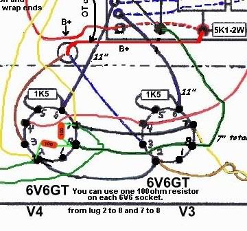
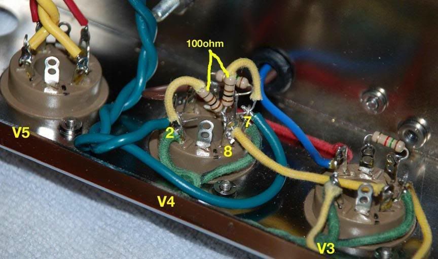
    Hi, i am building a Mission amp 5E3 and there is a suggestion to put the 100ohm resistors on pins 2 - 8 and 7-8 instead of the way its shown on the orig drawing. I am new at this so i have re-drawn it and wondering if it makes sense the way i have it.

    a


  • #2
    Hi angelodp

    Bruce just means to use pin 8 as a handy anchor point for the ground side of the 100R artificial heater 'ground-reference' resistors (albeit that these are elevated to the 6V6 cathode voltage). Pin 8 isn't connected to anything on a 6V6, so that socket pin is available as a spare terminal lug.

    The way you have drawn it will work also. It's just that Bruce's idea is probably tidier-looking once its done
    Building a better world (one tube amp at a time)

    "I have never had to invoke a formula to fight oscillation in a guitar amp."- Enzo

    Comment


    • #3
      Pic

      I was simply trying to establish a layout for the pic that Bruce sent. He includes this pic which does not match the layout, so I went ahead and redrew the layout to check things. I know there are many ways to do circuits and so i am just double checking that I have it correct.

      Comment


      • #4
        I am currently building a Mission kit and am wondering what these 2 resistors do. They are not in the original 5E3 layout. Do they change the tone, decrease hum, etc?

        Comment


        • #5
          Originally posted by scottb1966 View Post
          I am currently building a Mission kit and am wondering what these 2 resistors do. They are not in the original 5E3 layout. Do they change the tone, decrease hum, etc?
          They are necessary when wiring up a heater winding that does not have a centre tap. They act as an artificial centre tap/ground reference point for the heater voltage, and they ensure that both sides of the heater winding are swinging at more-or-less precisely opposite VAC swings with respect to each other, so that you cancel-out any possible heater AC hum in the tubes (hum which would otherwise be induced into the signal path either through the tubes themselves, and/or through stray EMF from the heater wires into other signal wires)
          Building a better world (one tube amp at a time)

          "I have never had to invoke a formula to fight oscillation in a guitar amp."- Enzo

          Comment


          • #6
            Originally posted by tubeswell View Post
            ... Pin 8 isn't connected to anything on a 6V6, so that socket pin is available as a spare terminal lug.
            Pin 8 is the cathode, hence the connection for the heaters being elevated. (Cathode bias on the 5E3 of course).
            "In theory, there is no difference between theory and practice. In practice there is."
            - Yogi Berra

            Comment


            • #7
              Originally posted by tubeswell View Post
              They are necessary when wiring up a heater winding that does not have a centre tap. They act as an artificial centre tap/ground reference point for the heater voltage, and they ensure that both sides of the heater winding are swinging at more-or-less precisely opposite VAC swings with respect to each other, so that you cancel-out any possible heater AC hum in the tubes (hum which would otherwise be induced into the signal path either through the tubes themselves, and/or through stray EMF from the heater wires into other signal wires)
              Thanks, I will solder them in. I am about 1/2 done. Finished the turret board last night. Should have it running by the weekend.

              Comment


              • #8
                Originally posted by JoeM View Post
                Pin 8 is the cathode, hence the connection for the heaters being elevated. (Cathode bias on the 5E3 of course).
                Right you are - crikey my lapses are getting awful. I was thinking of Pin 1 when I wrote that.
                Last edited by tubeswell; 06-22-2009, 07:35 PM.
                Building a better world (one tube amp at a time)

                "I have never had to invoke a formula to fight oscillation in a guitar amp."- Enzo

                Comment


                • #9
                  All done

                  I soldered it in as shown and I am all done.... amp sounds great. Dead quiet on HB's with an open chassis. Should be even quieter once in the cabinet. I was thinking of putting a shield on the inside on the panel that screws into the cab in front of the chassis. I guess a copper or aluminum foil will work. Do the vintage 5E3's have that shielding??

                  ange

                  Comment


                  • #10
                    Originally posted by angelodp View Post
                    I soldered it in as shown and I am all done.... amp sounds great. Dead quiet on HB's with an open chassis. Should be even quieter once in the cabinet. I was thinking of putting a shield on the inside on the panel that screws into the cab in front of the chassis. I guess a copper or aluminum foil will work. Do the vintage 5E3's have that shielding??

                    ange
                    There isn't a huge amount of gain in these amps that which would require an abnormal amount of special shielding.
                    However, I do use some Al foil, HVAC tape on the back upper valance panel when I build my own kits.
                    I don't remember seeing any foil or Faraday shielding on old amps like this but many old-ass tweed amps had a strip of, "gasp" , asbestos sheeting under that rear upper panel!
                    Mostly to keep the hot running power tubes from cooking the cheap 1/4" thick plywood panel.
                    Bruce

                    Mission Amps
                    Denver, CO. 80022
                    www.missionamps.com
                    303-955-2412

                    Comment

                    Working...
                    X