Announcement

Collapse
No announcement yet.

First build completed - 5e3 - catode current issues

Collapse
X
 
  • Filter
  • Time
  • Show
Clear All
new posts

  • First build completed - 5e3 - catode current issues

    Hi all,

    I have enjoyed my first experience building an amp. Although, I have a question in regard to the 6v6 cathode current.

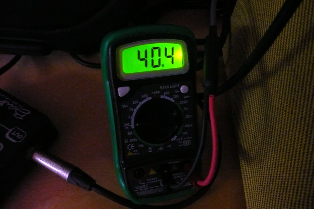
    I have toke these measurements with a bias probe:


    40.4Ma and 40.7ma on V3 and V4 with a 250ohm resistor
    6v6 pin 3=326V X 0.040= 13w

    37.6MA and 37.9Ma on V3 and V4 with a 270ohm resistor
    6v6 pin 3=326v X 0.037=12w

    Are any of these cathode currents power tubes friendly?

    Thanks a lot!

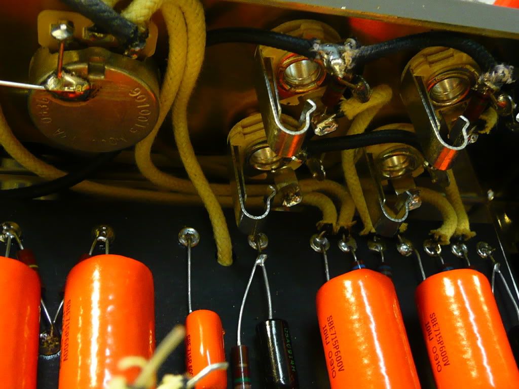
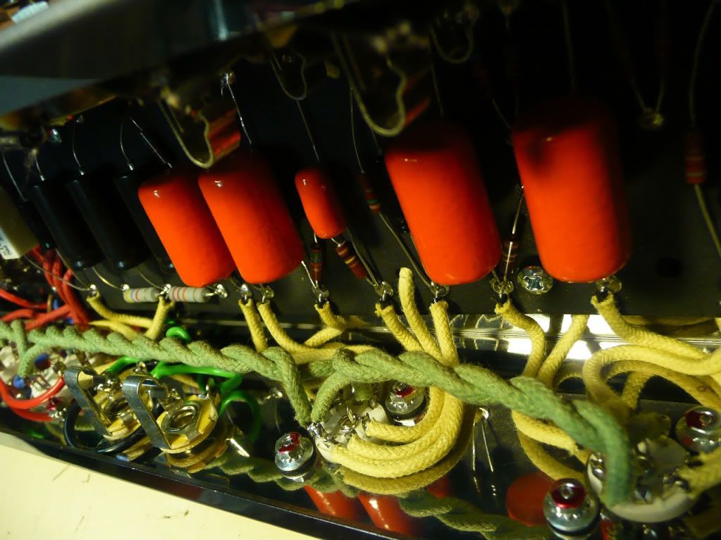
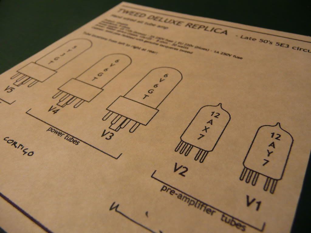
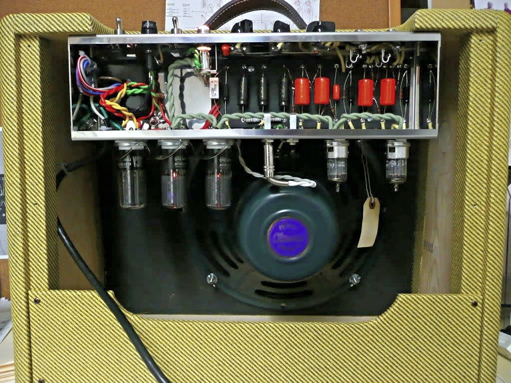
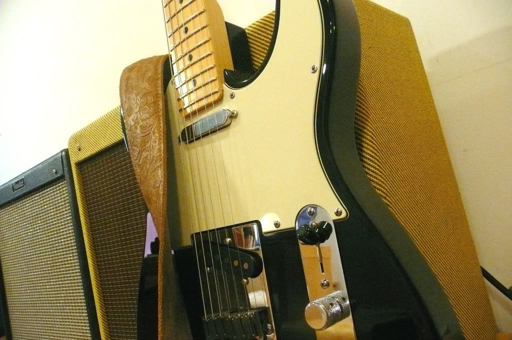
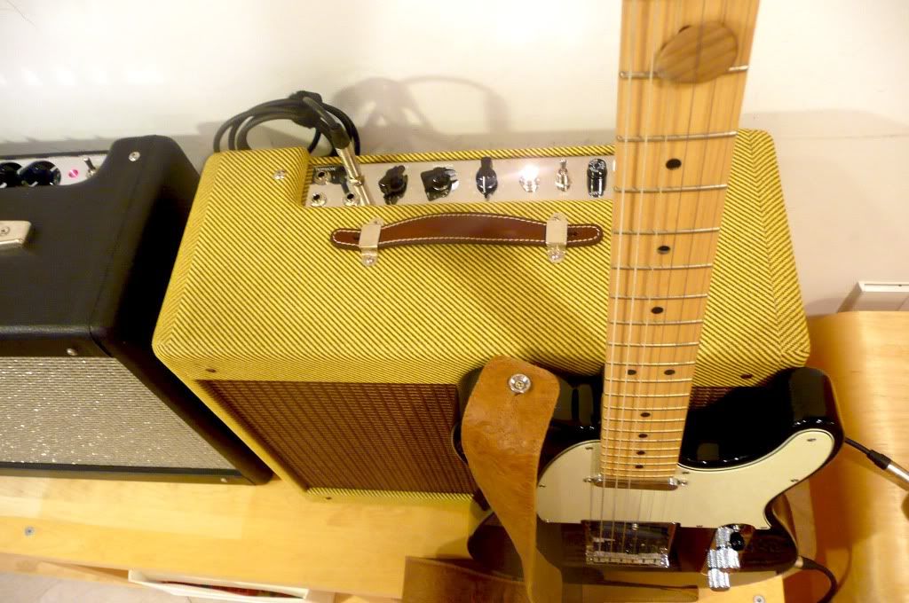
    Below are a few pics of my home build:


    Last edited by tweed; 10-06-2009, 02:49 PM. Reason: more info

  • #2
    Hi there

    In order to verify the tube's idle current, what is needed is the plate-to-cathode voltage of each respective tube, and the voltage across the cathode resistor, as well as the actual accurately-measured resistance of the cathode resistor. Without this we can't say for sure what power the tube is dissipating.

    Furthermore, without knowing what the screen current draw is of each tube, we can't work out the plate dissipation at idle is if we are merely looking at the total tube current draw on each tube (Tube current = Plate current + Screen current).

    What method did you use to measure the current that you have specified?
    Building a better world (one tube amp at a time)

    "I have never had to invoke a formula to fight oscillation in a guitar amp."- Enzo

    Comment


    • #3
      In most cases a 250ohm cathode resistor will be OK up to plate (to ground) voltages of <380vdc, you seem to have less than that, as long as you are 40mA, or less you are OK. The 270ohm looks ideal.

      Comment


      • #4
        Hi there, Thanks for the replies.

        I have used a bias probe plugged between tube and socket. This probe has a 1 Ohm shunt resistor which works as a simple current-to-voltage converter.

        As per instructions, 40mV multimeter reading corresponds to 40mA tube current.

        I read a lot of things and at this pois I don't have a clear idea how to determine a good bias point...

        Comment


        • #5
          "I read a lot of things and at this pois I don't have a clear idea how to determine a good bias point..." for you're amp, as long as plate to ground voltage is <380vdc, 35-40mA is a good bias point.

          General 'rule of thumb' is bias to 80-90% plate dissipation for cathode biased amps, like 5E3. Fixed bias amps might be biased to 50-70% dissipation.

          However as with most general rules, there are exceptions, that's where experience comes in. Some 5E3 run more like 14W dissipation, some late models run more than that & should really be fitted with a larger cathode resistor. If you had concerns about plate dissipation and your amp ate tubes, or the metal plates glow red/orange, you could try 300-330ohms for the cathode resistor (not that you need to do this, unless perhaps you were trying a stiffer rectifier like 5V4). SF Champs run their 6V6 at 150% plate dissipation.

          As Tubeswell says, there will be some screen current in that 40.4mA, but this will be negligible (a couple of mA).

          At the end of the day, biasing is more about tone that meeting mathematical perameters (as long as you're not burning things up that is)...IF you liked your cathode biased amp at 70% dissipation then that would be right for YOU. I wouldn't really recommend less than 30mA for your 5E3 as tone may become thin/sterile, plate voltage would also be pushed higher than what is deemed "classic" 5E3 voltage. One of the benefits of cathode bias is that, if your voltages are suitable (yours are), it's pretty much a case of "fit & forget".

          Comment


          • #6
            Originally posted by tweed View Post
            As per instructions, 40mV multimeter reading corresponds to 40mA tube current.
            which is about 38mA plate current (taking 2mA off for the screen current) for each tube


            Originally posted by tweed View Post
            I read a lot of things and at this point I don't have a clear idea how to determine a good bias point...
            What is the actual accurate measured resistance (in Ohms) of the cathode resistor? (You will need to unsolder the cathode bypass cap to measure this). The bias in these cathode-biased amps is set by the resistor.

            Cement/wirewound/power resistors hardly ever come off the production line all measuring the 'stated' resistance. Get a handful of 5W or 10W power resistors and measure their resistances. You can substitute them into your amp to tweak the bias point. Whilst the difference between a '270R' resistor that actually measures 255R, and another '270R' resistor that measures 265R will not be much in terms of setting the bias point, the difference will be a bit more noticeable compared to a '270R' resistor that actually measures 295R, and so on.

            The bias voltage is a reflection of the resistance and the current through the resistor (Volts = Amps x Ohms).

            So you measure the idle DC voltage between the cathode and the ground (with the amp on and the tubes plugged in), and you divide that by the actual measured resistance of the resistor (which you have already measured with the cathode bypass cap disconnected/unsoldered - if you try to measure it with the cap connected, the R-meter reading will be affected by the paralleled series-resistance of the cap) and you get the tube current.

            Of course if you are measuring the tube current this way with a shared cathode resistor, the current being drawn through the resistor will be flowing through both tubes in parallel, so you will have to divide the resultant calculated current by 2 to get the estimated tube current per tube.

            As has already been mentioned, you need to deduct the screen current from the tube current to obtain the estimated plate current, which you need for determining actual plate dissipation.

            The plate dissipation is then obtained by multiplying the plate-to-cathode DC voltage (at idle) with the estimated plate current. (Hence you want to know the cathode DC voltage at idle in order to calculate the plate-to-cathode voltage).

            But the way you have measured tube current with your bias-probe is giving you an accurate reading of the tube current per-tube. (In this regard I assume your bias-probe is measuring tube current, which it will be if the 1R resistor is in series with the cathode (Pin 8). If it was in series with the plate (Pin 3) it would measure plate-current equivalent in mV - which is important for calculating dissipation. Likewise if the 1R was in series with the screen (Pin 4) you'd get the screen-current equivalent in mV. However if the bias probe resistor it is a poxy little 1% 0.6W metal film resistor, its breakdown voltage is something like 360V, so the manufacturer is probably unlikely to wire it to the plate pin or the screen pin, hence you will have to deduct screen current from the measured tube current to obtain the plate current, as has already been mentioned)

            There is another way of measuring plate current - by measuring the voltage dropped through the OT primaries, after you have measured the DC resistance of each side of the OT primary. However that method is riskier because the voltages are a lot higher.

            As for calculating the bias point in a more technical way, Merlin B has a couple of good articles on the Valve Wizard site on designing output stages (including working with tube characteristics charts).

            As rule of thumb goes, if your amp sounds good and the tubes aren't red-plating, then it should be fine as MWJB already mentioned.
            Building a better world (one tube amp at a time)

            "I have never had to invoke a formula to fight oscillation in a guitar amp."- Enzo

            Comment


            • #7
              Very Enlightening, thank you for your time guys.

              Comment


              • #8
                Nobody mentioned it but you wiring is very neat and lead dress is excellent.
                WARNING! Musical Instrument amplifiers contain lethal voltages and can retain them even when unplugged. Refer service to qualified personnel.
                REMEMBER: Everybody knows that smokin' ain't allowed in school !

                Comment


                • #9
                  Originally posted by loudthud View Post
                  Nobody mentioned it but you wiring is very neat and lead dress is excellent.
                  Thanks a lot!

                  I was by first build I arrived yesterday to the vintage electronics world. I am happy with the result. I tried to make it nice Aesthetically, I wish I have more technical knowledge to fully understand the circuits.

                  I found out that build amps can be very addictive, unfortunately this hobby is a bit expensive.

                  Best

                  Comment


                  • #10
                    I'll second Loudthud's remark. very nice job with this build. Is that locktite on the socket mounting nut's? Again, nice job. I like the tele too. RD

                    Comment


                    • #11
                      Originally posted by Rocketrob View Post
                      I'll second Loudthud's remark. very nice job with this build. Is that locktite on the socket mounting nut's? Again, nice job. I like the tele too. RD
                      Thanks Rocketrob. I have used nails polish it seems to do the job...

                      Comment


                      • #12
                        Hi again, Yesterday I have took final voltage readings on my amp.

                        My bias probe shows me now 38ma with a 270ohms cathode resistor. What do you think, considering the voltages below?

                        5Y3
                        Pin 2: 388V
                        Pin 8: 388V

                        6V6's
                        Pin 3: 383V
                        Pin 4: 340V
                        Pin 8: 20V
                        Pin 3 to Pin 8: 360V

                        12ax7
                        Pin 1: 157V
                        Pin 6: 158 V

                        12ay7
                        Pin 1: 116V
                        Pin 6: 176V

                        Comment


                        • #13
                          Looks fine.

                          Comment


                          • #14
                            Thanks! this is the way it sound, half blast with a 97 Gibson Studio DC, straight in...

                            [ame="http://www.youtube.com/watch?v=4WGnCmHcKk4&feature=player_embedded"]YouTube - Home made Tweed Deluxe[/ame]

                            Comment

                            Working...
                            X