Announcement

Collapse
No announcement yet.

Adding pairwise fuse protection while still having external single tube bias check...

Collapse
X
 
  • Filter
  • Time
  • Show
Clear All
new posts

  • Adding pairwise fuse protection while still having external single tube bias check...

    Alright so on a 4 tube(6L6) PP power amp build I am doing, I wanted to add fuse protection for the tubes. I figured by fusing each pair, if one goes out it will take an opposite tube out of action, so I could continue to play the amp when gigging(although now at half power and mismatched impedance, but it would get me through the gig).

    Yet I want the power amp tubes to still be individual biased, and I want to have individual bias check taps on the outside of the amp. I'm kinda stumped on how I can implement this, as it seems I would have to fuse each tube individually, which isn't what i want to do. Or I would have to ditch my individual bias check points, which isn't what i want to do.

    The only thing I could really think of was adding a switch that I could flip to 'bias' when biasing, that would bypass the fuse system and switch all the tubes over to the 1R resistors used to check the bias. Then, when the switch is flipped back to run, it switches back over to the fuse system.

    Is their a different/easier way to implement this?

  • #2
    Originally posted by DIY_Guy View Post
    Is their a different/easier way to implement this?
    Changing your output tubes before they get to the point where they will implode? 2CW
    Building a better world (one tube amp at a time)

    "I have never had to invoke a formula to fight oscillation in a guitar amp."- Enzo

    Comment


    • #3
      Originally posted by DIY_Guy View Post
      I'm kinda stumped on how I can implement this, as it seems I would have to fuse each tube individually, which isn't what i want to do. Or I would have to ditch my individual bias check points, which isn't what i want to do.
      I'm probably just being dense today, but I can't see that how you fuse it has anything to do with how you sense current and bias.

      Fuses pop when the I^2*t energy delivered to the fuse element or the I^2*R power from current raises the element's temp enough to melt. Below melting, it pretty much is just a wire, at least to a first approximation. If you have a sampling resistor in series with it and are looking at the voltage across the resistor to determine current, then the resistor always tells the correct current, either when operating or when the fuse is popped, in which case the current is zero.

      Tell me what I'm missing, because I have the feeling I'm missing something that's bothering you.
      Amazing!! Who would ever have guessed that someone who villified the evil rich people would begin happily accepting their millions in speaking fees!

      Oh, wait! That sounds familiar, somehow.

      Comment


      • #4
        Ground each cathode through a 0.25 Amp fuse and a 1r 1W resistor, in that order.
        Whatever you measure from the top pin of the resistor to ground will be accurate.
        I think the fuse will blow before the resistor, but in any case, after a catastrophic tube failure, replace the resistor involved with a fresh one.
        Juan Manuel Fahey

        Comment


        • #5
          I think what's bothering you is that you cannot connect your bias check resistors to ground.
          You can do it if you go from each cathode -> individual bias sense R -> common fuse -> ground.
          You can still check bias from ground to cathode as long as the resistance of the fuse is neglegible compared to the sense R.

          Hope this makes sense, too tired to make a drawing...

          Cheers,
          Albert

          PS: J M Fahey, I think he wants to fuse each PAIR of tubes while still maintaining individual bias check points.

          Comment


          • #6
            Hi Albert, you are absolutely right, that's what he asked.
            What I didn't detail (It's already 11 PM in Buenos Aires and I'm tired) is that I am somewhat paranoid about electrical safety.
            The sequence I suggested lets the measuring jack "cold", tied to ground through a 1 ohm resistor, in case of tube failure, specifically an internal short, because the fuse opens.
            Putting the resistor(s) *above* the fuse, will let them "hot" when it blows, leaving that same point connected to around 450V through that same shorted tube.
            Remember the "tester" will expect to see a few millivolts there; with good luck he will burn his multimeter ; and with bad luck .......
            Sorry for not having expressed myself more clearly.
            PS: are you *the* Albert Kreuzer that designs Tube and SS Bass preamps?
            Juan Manuel Fahey

            Comment


            • #7
              i have done exactly this in my 300w bass amp build here http://music-electronics-forum.com/t15682/

              i tied the cathodes of each pair together, then through the fuse, then through 5ohm resistor (2x10ohm in series actually) the test points go from either side of the resistor. works great.

              Comment


              • #8
                Not directly on topic, but close.

                A few years ago, I messed with using high voltage power MOSFETs as adjuncts to tube amps. There are an assortment of complaints about this from non-believers in silicon, but with a little thought they can be very useful as well as non-polluters of tone.

                One application that is simple and works very well is to use them as a current-stop on the cathodes of power tubes. If the MOSFET is either off and non-conducting or on and equal to a resistance of a few ohms, then they don't impact sound quality. What's interesting and worth the effort is that you can make them go between on and off by switching perhaps 12Vdc referenced to ground on their gate. This makes for a much safer standby switch if you use standby switches, because the switch itself does not need to be wired with B+ voltages.

                Beyond that, if you have already set up a MOSFET to stop tube conduction, you can use it for other things. If you use a 1 ohm sampling resistor to ground in series with the tube cathode and MOSFET, you can read the tube's current to bias it, just as you would if you didn't use the MOSFET. The alert reader will already have leapt to the application - you can also read the tube current all the time, and sense when it's bigger than X for longer than Y and turn off the MOSFET, forcing the tube to stop conducting. This works even if the tube has shorted. Power MOSFETs which have multi-ampere continuous current ratings are easy to find and cheap.

                You can use one sense resistor for all tubes, or one resistor per tube, and one MOSFET for each tube or one for all tubes, as you like. You can also use simple CMOS logic to sense when, say, one tube goes overcurrent and shut down all tubes, or only pairs, or whatever you want to hook up the logic for. You can make it latching so you have to power-cycle the AC to reset it, or put in a reset button, or whatever you can imagine and set up. You can add some time delay to prevent trips on transients easily enough; this can be anything from a few microseconds up to several seconds.

                I built up one of these, and the first prototype worked. I tested it by shorting the grid bias to a tube. The thing shut down in less than a millisecond by oscilloscope, instantly to a human. I view this application as more of a power transformer and output transformer saver than a tube saver, although it will save tubes when the tube is fine but the bias supply shorts or opens. One could extend this to sensing case temps, etc. if one were inclined. I have not yet figured out a girlfriend- or bass player- sensor to turn off the amp in case of tinkering, but I'm sure something could be worked out.

                This is probably another of those things which involves the excessive application of technology to some situation which is hardly ever a problem (a speciality of mine! ) but it does work and well.
                Amazing!! Who would ever have guessed that someone who villified the evil rich people would begin happily accepting their millions in speaking fees!

                Oh, wait! That sounds familiar, somehow.

                Comment


                • #9
                  Originally posted by J M Fahey View Post
                  The sequence I suggested lets the measuring jack "cold", tied to ground through a 1 ohm resistor, in case of tube failure, specifically an internal short, because the fuse opens.
                  Putting the resistor(s) *above* the fuse, will let them "hot" when it blows, leaving that same point connected to around 450V through that same shorted tube.
                  Remember the "tester" will expect to see a few millivolts there; with good luck he will burn his multimeter ; and with bad luck ....... :thumbsdown
                  You could provide a "fuse open" indicator like on some Marshalls, so you wouldn't stick your mV meter in there when the fuse has gone.

                  Also see R.G.'s post, very useful ideas there.


                  Originally posted by J M Fahey View Post
                  PS: are you *the* Albert Kreuzer that designs Tube and SS Bass preamps?
                  You mean this Albert Kreuzer guy? Yep, that's me.

                  Cheers,
                  Albert

                  Comment


                  • #10
                    Thanks a bunch for all the answers. I think I came up with a solution using all of your suggestions.

                    R.G., isn't that kind of like what Hughes and Kettner use in their tube protection circuits?

                    Comment


                    • #11
                      I'm unclear why you would want to have 2 tubes sharing the same fuse - what's the benefit over fusing them individually?
                      A fuse per tube allows you to use the smallest possible fuse value - you'd have to use twice that value for 2 tubes, so a fault condition could carry on for longer, and a red plating tube might carry on for a long while until it finally shorts, which will put a lot of stress on to your transformer set.
                      Whatever, remember that a quick blow fuse can be used, as there are no caps to charge up.
                      At full output, I've measured currents above 250mA per 6L6GC, so use an F315mA type.
                      My band:- http://www.youtube.com/user/RedwingBand

                      Comment


                      • #12
                        Originally posted by R.G. View Post
                        Not directly on topic, but close.

                        A few years ago, I messed with using high voltage power MOSFETs as adjuncts to tube amps. There are an assortment of complaints about this from non-believers in silicon, but with a little thought they can be very useful as well as non-polluters of tone.

                        One application that is simple and works very well is to use them as a current-stop on the cathodes of power tubes. If the MOSFET is either off and non-conducting or on and equal to a resistance of a few ohms, then they don't impact sound quality. What's interesting and worth the effort is that you can make them go between on and off by switching perhaps 12Vdc referenced to ground on their gate. This makes for a much safer standby switch if you use standby switches, because the switch itself does not need to be wired with B+ voltages.

                        Beyond that, if you have already set up a MOSFET to stop tube conduction, you can use it for other things. If you use a 1 ohm sampling resistor to ground in series with the tube cathode and MOSFET, you can read the tube's current to bias it, just as you would if you didn't use the MOSFET. The alert reader will already have leapt to the application - you can also read the tube current all the time, and sense when it's bigger than X for longer than Y and turn off the MOSFET, forcing the tube to stop conducting. This works even if the tube has shorted. Power MOSFETs which have multi-ampere continuous current ratings are easy to find and cheap.

                        You can use one sense resistor for all tubes, or one resistor per tube, and one MOSFET for each tube or one for all tubes, as you like. You can also use simple CMOS logic to sense when, say, one tube goes overcurrent and shut down all tubes, or only pairs, or whatever you want to hook up the logic for. You can make it latching so you have to power-cycle the AC to reset it, or put in a reset button, or whatever you can imagine and set up. You can add some time delay to prevent trips on transients easily enough; this can be anything from a few microseconds up to several seconds.

                        I built up one of these, and the first prototype worked. I tested it by shorting the grid bias to a tube. The thing shut down in less than a millisecond by oscilloscope, instantly to a human. I view this application as more of a power transformer and output transformer saver than a tube saver, although it will save tubes when the tube is fine but the bias supply shorts or opens. One could extend this to sensing case temps, etc. if one were inclined. I have not yet figured out a girlfriend- or bass player- sensor to turn off the amp in case of tinkering, but I'm sure something could be worked out.

                        This is probably another of those things which involves the excessive application of technology to some situation which is hardly ever a problem (a speciality of mine! ) but it does work and well.
                        Since I'm not skilled enough I don't have any clue how those mosfets work and how they're supposed to be installed. But it's sounds really great and interresting. Do you have a sketch or schematic for your described technique? I'm eager to learn some more.

                        Comment


                        • #13
                          Originally posted by DIY_Guy View Post
                          R.G., isn't that kind of like what Hughes and Kettner use in their tube protection circuits?
                          I don't know. I did the work on this back in '99 or so. I haven't seen what Hughes and Kettner do, but I wouldn't be surprised.

                          Kevin O'Connor uses a MOSFET for standby in his TUT books.

                          Something like this would be pretty obvious to a power supply designer (which I used to be) if you told him you wanted to shut down on tube overcurrents in a tube amp. The tricks of using a small sampling resistor inside a feedback loop to sense currents, then doing analog and digital stuff unique to the situation to turn off/reset/etc. on sense are widespread in the power supply community. All that's unique about what I did was to recognize the situation, and apply the tricks in a somewhat non-traditional environment.
                          Amazing!! Who would ever have guessed that someone who villified the evil rich people would begin happily accepting their millions in speaking fees!

                          Oh, wait! That sounds familiar, somehow.

                          Comment


                          • #14
                            Originally posted by txstrat View Post
                            Since I'm not skilled enough I don't have any clue how those mosfets work and how they're supposed to be installed. But it's sounds really great and interresting. Do you have a sketch or schematic for your described technique? I'm eager to learn some more.
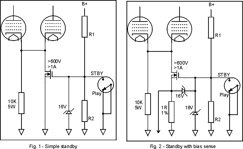
                            I drew up a schematic.

                            A MOSFET is a resistor between the drain and source. A voltage impressed between the gate and source causes the resistance to change from near-infinite (an open circuit, essentially) down to the lowest it can be, which is the Rds (resistance from drain to source) on the datasheet for its type. A suitable device for this application might be the Toshiba 2SK3564, which DigiKey sells for $1.46. It is rated at a maximum voltage of 900Vdc and a maximum current of 3A. When fully turned on, its Rds is 3 ohms.

                            A suitable setup might be like this:
                            It's a version of something I put on GEOFEX in 2000:
                            MOSFET Follies, which also contains a number of other MOSFET uses in tube amps. Other people have tried these with good success.

                            The MOSFET is conceptually just an electronic switch which is activated by either 0V or about 10-20V on its sensitive electrode, the gate. It interrupts the cathode side of the tubes, and shuts down all B+ current from the tube.

                            The 10K resistor left in parallel with the MOSFET is there as a preventer for a possible degradation mode in tubes left with heaters on and truly zero current for long periods of time. This degradation is by no means certain, but it's easy to get around by leaving some small current running in standby, hence the 10K resistor.

                            The 16V zener from gate to source prevents any transient voltages from damaging the MOSFET gate. R1 and R2 set the gate enhancement voltage from B+ and the 16V zener limits this voltage. Picking R1 and R2 is somewhat ambiguous. If you rely on the 16V zener to set the gate voltage, then R2 can be almost any value that lets more than 16V appear on the gate by voltage divider action. You can also pick R1 and R2 to make a nominal voltage appear without turning on the zener. I personally would set R1 and R2 to get about 16-18V with a nominal B+ value. This ensures that there is enough turn-on voltage if B+ is a little low, and also that the zener will regulate the max voltage. Currents of 0.5 to 1 ma in R1 and R2 are fine.

                            I set up the standby switch to shunt the gate drive to ground, instead of interrupting the voltage from B+. It can be done either way. The shunt-to-ground setup leaves the amp on and usable if the switch fails open. A switch opening the path to R1 would leave the amp off and not usable - but protected - if the switch fails open.

                            In Fig. 2, the basic standby has a 1 ohm bias sensing resistor added. I added a second 16V zener as belt-and-suspenders from the gate to the source. The 16V zener to ground would probably prevent any problems with only a 1 ohm in series to the source, but the 1 ohm is probably wirewound and could conceivably produce enough of an inductive kick to kill the gate. Maybe.

                            This second figure is the departure point for the fancy shutdowns. You sense the current in the bias sampling resistor, and anything else you want, and use that sense to drive logic circuits which replace R1/R2 and the switch, turning the MOSFET on by driving the gate high when you want it on, and low when you want it off.

                            Did that help clear things or muddy them?

                            Update: I had to correct the figure. I labeled "Play" and "Standby" backwards.
                            Last edited by R.G.; 12-07-2009, 02:50 PM. Reason: Doh!!
                            Amazing!! Who would ever have guessed that someone who villified the evil rich people would begin happily accepting their millions in speaking fees!

                            Oh, wait! That sounds familiar, somehow.

                            Comment


                            • #15
                              Hi RG, thanks.
                              *Very* interesting and useful post, opens a myriad of possibilities.
                              I'm personally experimenting a lot with HV MosFets too.
                              By the way , are you RG "Keen" or it's just a coincidence?
                              Juan Manuel Fahey

                              Comment

                              Working...
                              X