 Tweet
Tweet
Hello all. This is my first post.
I just recently finished building my 1st amplifier. A JTM45 type pre on a EL84 Marshall 18watt power. I loved the experience of building this amp. The reason I built the amp was because I wasn't too happy with my Fender Red Knob Twin amp. I find that this Fender is just lacking "feeling". Don't know how else to explain it.
I started to play around with the Fender today to see if I can make some improvements to the tone. I Started by removing the 2 inner power tubes effectively cutting the power in half. I also swapped the 12AT7 PI with a 12AX7. I am definitely heading in the right direction, but It is still missing something.
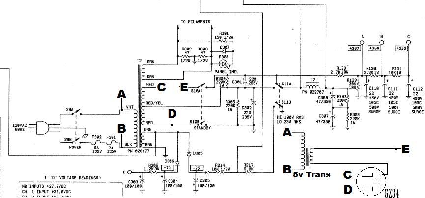
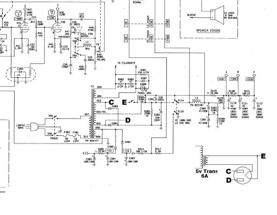
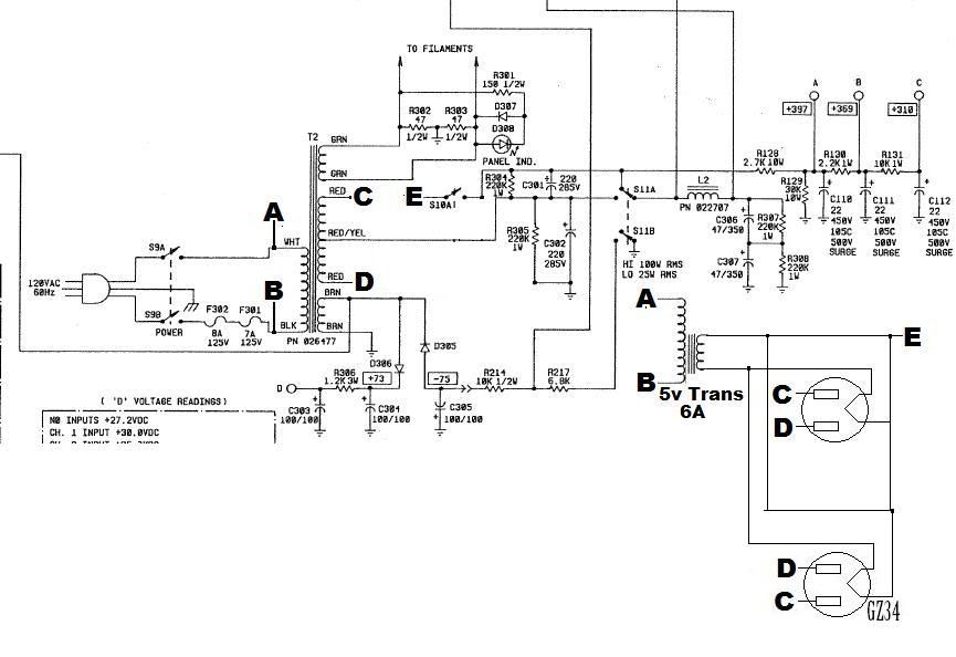
Before I resort to gutting the amp I would really like to try one last thing. I would really like to squeeze a GZ34 rectifier into the amp and remove the diode rectifier. Can this be done??
I have 2 extra 8 pin sockets since I removed 2 power tubes. I will also have to add a 5v Transformer for the GZ34's heater. I quickly cut up the schematic and added the GZ34 but I'm not sure if it will work with this amps power scheme. Here is what I have:
MODIFIED:
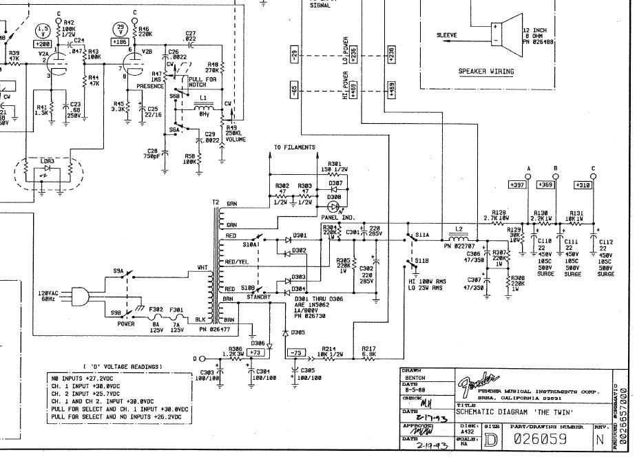
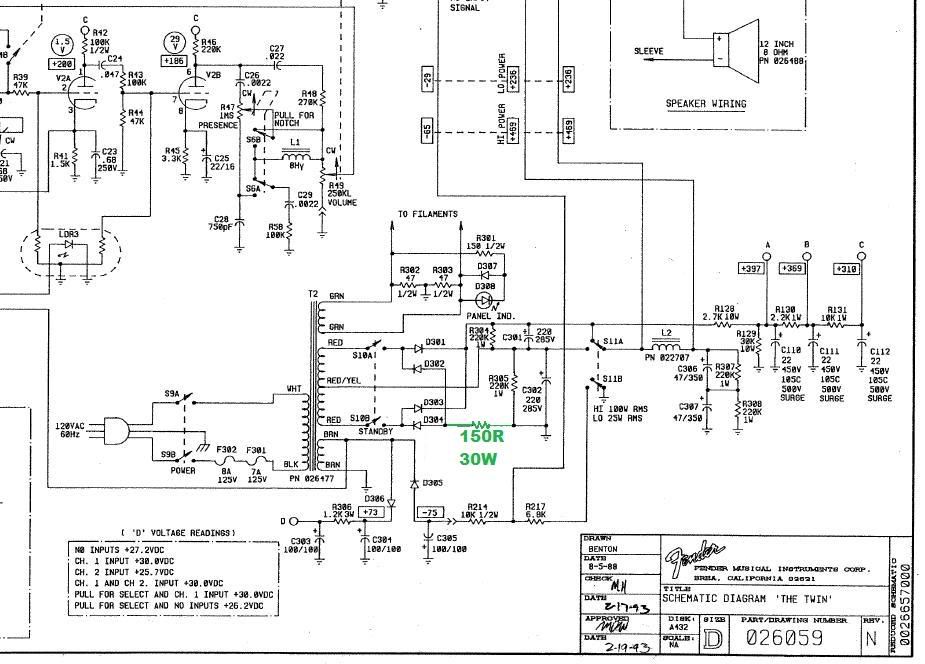
ORIGINAL
I appreciate any advice.
BR
Seth
I just recently finished building my 1st amplifier. A JTM45 type pre on a EL84 Marshall 18watt power. I loved the experience of building this amp. The reason I built the amp was because I wasn't too happy with my Fender Red Knob Twin amp. I find that this Fender is just lacking "feeling". Don't know how else to explain it.
I started to play around with the Fender today to see if I can make some improvements to the tone. I Started by removing the 2 inner power tubes effectively cutting the power in half. I also swapped the 12AT7 PI with a 12AX7. I am definitely heading in the right direction, but It is still missing something.
Before I resort to gutting the amp I would really like to try one last thing. I would really like to squeeze a GZ34 rectifier into the amp and remove the diode rectifier. Can this be done??
I have 2 extra 8 pin sockets since I removed 2 power tubes. I will also have to add a 5v Transformer for the GZ34's heater. I quickly cut up the schematic and added the GZ34 but I'm not sure if it will work with this amps power scheme. Here is what I have:
MODIFIED:
ORIGINAL
I appreciate any advice.
BR
Seth
Comment