Announcement

Collapse
No announcement yet.

Need help identifying this amp

Collapse
X
 
  • Filter
  • Time
  • Show
Clear All
new posts

  • #31
    Good day friends…

    This is an old thread but I came across something interesting and wanted to document and update this thread.

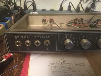
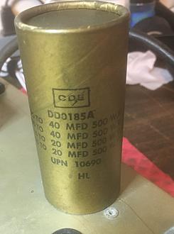
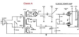
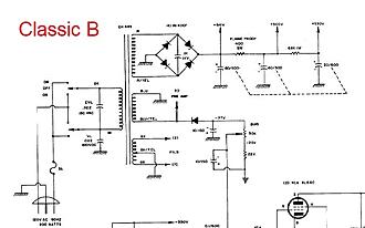
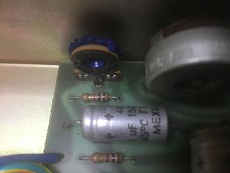
    A friend just gave me a very old Peavey “Classic” amp. Per Enzo’s reply in #2, you would think this is the “Classic A” version. There are two Bright and two Normal inputs. BUT… I noticed the canned cap is marked with 40/40/20/20. Hmmm… seems odd. That is not reflective of Classic A. The filter caps in the Version A schematic call for something else. I then noticed the cap connections. Once again, it did not resemble Version A. In fact, it looks just like Version B. The only difference in what I have vs Version B is that one of the resistors is NOT a 400 ohm, it is a 1K ohm. Another minor discrepancy.

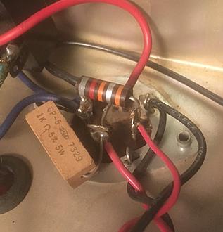
    The second thing I looked at was the Bias circuit. The PC board I have has components that resemble Version A. For the Bias circuit, there is a 1K resistor, the 50K pot, and nothing after the pot. One leg goes to ground. I think you all agree we do not like seeing one end of the pot going to ground. We would prefer the Classic B approach. So, the amp has some Version A and some Version B circuitry.

    The Version A schematic seems to show a switch on the rectifier diodes. Maybe a weird Standby switch? But neither A or B chassis ever had a Standby switch. Someone tried to install a Standby switch in my amp – bad mistake. I noticed he also wired up one side of the heaters to that switch. I will remove that switch.

    Version B appears to show Flyback diodes on the output tubes. My amp does not have those.

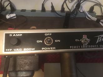
    One last thing I saw on the back of the chassis – there is a 3A stamp on the fuse. That was done with Version B.

    So… when you “Need help identifying this amp”, the answer might be a skosh more complex that just looking at the inputs!!

    It looks like I have a “tweener” version – perhaps it is a Classic A Plus!

    I was told this amp sparked and had issues the last time it was turned on. So I will evaluate what I have to see if it is worth salvaging. If so, I think I will do the following:

    - Remove the homemade standby switch and hard wire the heater to the output tubes.

    - Buy a new canned cap and mimic the Version B circuit.

    - Update the bias circuit to match Version B.

    - Do I need to add some screen resistors? I need to understand why this amp did not use them. I have seen many other amps with no screen resistors.

    - Maybe add some IN5408 Flyback diodes?

    If I can save this amp (as a donation to an up and coming young musician), what changes might you make?


    There you have it!

    Peavey_Classic_A_Schematic.pdf

    Peavey_Classic_B_Schematic.pdf


    Click image for larger version

Name:	IMG_4963.jpg
Views:	17
Size:	575.2 KB
ID:	997658

    Click image for larger version

Name:	IMG_4966.jpg
Views:	17
Size:	2.01 MB
ID:	997660

    Click image for larger version

Name:	IMG_4975.jpg
Views:	17
Size:	1.06 MB
ID:	997659

    Click image for larger version

Name:	IMG_4965.jpg
Views:	17
Size:	203.5 KB
ID:	997656

    Click image for larger version

Name:	Classic A Image.jpg
Views:	17
Size:	106.9 KB
ID:	997663

    Click image for larger version

Name:	Classic B Image.jpg
Views:	17
Size:	46.7 KB
ID:	997664


    Click image for larger version

Name:	IMG_4967.jpg
Views:	17
Size:	318.1 KB
ID:	997657
    It's not just an amp, it's an adventure!

    Comment


    • #32
      I think sometimes we fool ourselves and think of Version X, Version Y, etc, but when these things were being hand built in fairly low quantities there was definitely the possibility, if not certainty, of evolutions of the design or part substitutions based on supplies. Some of those changes made it to the "next version," some didn't.

      Comment


      • #33
        Thanks Glebert ...

        I understand incremental updates to a circuit. Its just that I had not seen a case where Peavey would make these types of changes (what I would consider a major tweak) to a current version. So clearly, there must be another version of this schematic (for Version A) out there somewhere. If I find it, I will post it.

        I have the amp working - yeah! I found an Accutronics 4FB2B1A tank in my bone yard and I believe this is what Peavey might have been using back in the day. So if anyone knows something to the contrary, let me know.

        For now, I installed an old set of Fender Grove Tubes 6l6gb tubes. The plate voltage is 418dc and I set the bias to 27mv. So they are around 60%? Good enough.

        The Tremolo is also working but its very week. I am not sure what the Trem pot does, so I'll research that.

        Click image for larger version

Name:	Tremolo.jpg
Views:	17
Size:	27.5 KB
ID:	997671
        It's not just an amp, it's an adventure!

        Comment


        • #34
          Hey Tom in my experience old Peaveys usually use 4EB2C1B reverb units, but see it the alt work!

          Comment


          • #35
            Originally posted by tedmich View Post
            Hey Tom in my experience old Peaveys usually use 4EB2C1B reverb units, but see it the alt work!
            Thanks Ted! Yes, I have some spare 4EB2C1B tanks and will try one of those. I do believe the Peavey Part number is 710-11114. I only mentioned the other tank as I saw a YouTube video on this amp and it had the other tank.

            The tank mounts on the back side of the chassis, through four existing screws. Of course, those do not align with the tank so I will either drill some new holes or mount the tank at the bottom of the cabinet and will extend the rca cables.
            It's not just an amp, it's an adventure!

            Comment


            • #36
              Well I still have an old 1976 Peavey classic in my shop. I remember that amp has the large can capacitor just like yours. I remember the plate voltage being close to or at 500v running tubes at 60% dissipation. I have used this amp to test questionable tubes in the past. I have seen cheap tubes react funny in this amp. So I knew not to run a certain batch of tubes in amps above 400-440v range. You know I think your plate voltage is significantly different than my amp that they probably have different transformers. Just caught my attention.
              When the going gets weird... The weird turn pro!

              Comment


              • #37
                Originally posted by DrGonz78 View Post
                Well I still have an old 1976 Peavey classic in my shop. I remember that amp has the large can capacitor just like yours. I remember the plate voltage being close to or at 500v running tubes at 60% dissipation. I have used this amp to test questionable tubes in the past. I have seen cheap tubes react funny in this amp. So I knew not to run a certain batch of tubes in amps above 400-440v range. You know I think your plate voltage is significantly different than my amp that they probably have different transformers. Just caught my attention.
                The transformer does have the marking of EH 449. So it is original. Two of the caps in the can are bad. So I will remove the can and use Axial Caps as the replacements. I've ordered parts today and hope to get back to this amp by next weekend.

                During the downtime, I will see if I can find the schematic that might have been created for this amp.
                It's not just an amp, it's an adventure!

                Comment


                • #38
                  FWIW: I don't like either of those bias supplies simply because, if the pot wiper becomes intermittent or the connection fails, you lose bias all together and tubes red plate. If you're going to modify the bias supply, there are better circuits to copy. I'd at least add a higher value resistor from the 1k in the bias supply to the junction of the 220K resistors at the grids.
                  Last edited by The Dude; Today, 12:36 AM.
                  "I took a photo of my ohm meter... It didn't help." Enzo 8/20/22

                  Comment


                  • #39
                    Originally posted by The Dude View Post
                    FWIW: I don't like either of those bias supplies simply because, if the pot wiper becomes intermittent or the connection fails, you lose bias all together and tubes red plate. If you're going to modify the bias supply, there are better circuits to copy. I'd at least add a higher value resistor from the 1k in the bias supply to the junction of the 220K resistors at the grids.
                    When I install bias pots in a bias supply I will install it in series but wired like a rheostat. Then if the wiper fails it goes full resistance and it actually makes your bias supply go up. Well at least this is how I have been approaching the issue. Is this advisable? Anyone else do it that way? I know some put the pot between ground but I just wire it in with the series resistor. I love the rheostat!
                    When the going gets weird... The weird turn pro!

                    Comment


                    • #40
                      That works fine in most all cases. The only thing a person needs to be concerned about is that the overall voltage divider from supply to ground doesn't draw too much current at it's lowest possible resistance, which is rarely an issue if you use large enough value resistors in the divider. Your idea is certainly a better option than the supply in this Peavey. Bias is more or less a reference voltage. There is very little current draw on the supply. There are lots of ways to build a bias supply- IMO, none worse than the one in this amp.
                      Last edited by The Dude; Today, 01:48 AM.
                      "I took a photo of my ohm meter... It didn't help." Enzo 8/20/22

                      Comment


                      • #41
                        How about something like this ??

                        Click image for larger version

Name:	Classic Bias.jpg
Views:	0
Size:	841.0 KB
ID:	997689
                        It's not just an amp, it's an adventure!

                        Comment


                        • #42
                          Tom,
                          That drawing has the same issue. Notice if the wiper goes open (as does happen with many pots, when they get dirty, you lose bias voltage to the tubes. If you wire the pot as a rheostat (as Gonz suggested), that should work. Or, add another large value resistor here (see drawing) so that if the pot goes wonky you still have protection from red plating tubes.

                          Click image for larger version  Name:	Classic-Bias.jpg Views:	0 Size:	116.6 KB ID:	997692
                          Last edited by The Dude; Today, 04:01 AM.
                          "I took a photo of my ohm meter... It didn't help." Enzo 8/20/22

                          Comment


                          • #43
                            Sorry.... I probably should have opened a new thread for this bias question....

                            Ok, I got out my bread board and fired up the power supply. Using Dude's drawing, here is what I tested.

                            I went back to a 10K for R1 and used a 100K for the resistor that goes across the pot. So I now have a range of -62.7 volts to -13.7 volts. Perhaps I could tighten that up a bit. The target is to hit -55 volts give or take a few.

                            One thing I noticed, when I increase the voltage (as I near the -13.7 point), the input voltage drops. So I guess that is telling me this circuit is pulling a bit too much current. So perhaps tomorrow I will double all the values and see if I get the same results.

                            Click image for larger version

Name:	Classic Bias.jpg
Views:	0
Size:	566.6 KB
ID:	997697
                            It's not just an amp, it's an adventure!

                            Comment

                            Working...
                            X