Announcement

Collapse
No announcement yet.

12DW7 Reverb

Collapse
X
 
  • Filter
  • Time
  • Show
Clear All
new posts

  • 12DW7 Reverb

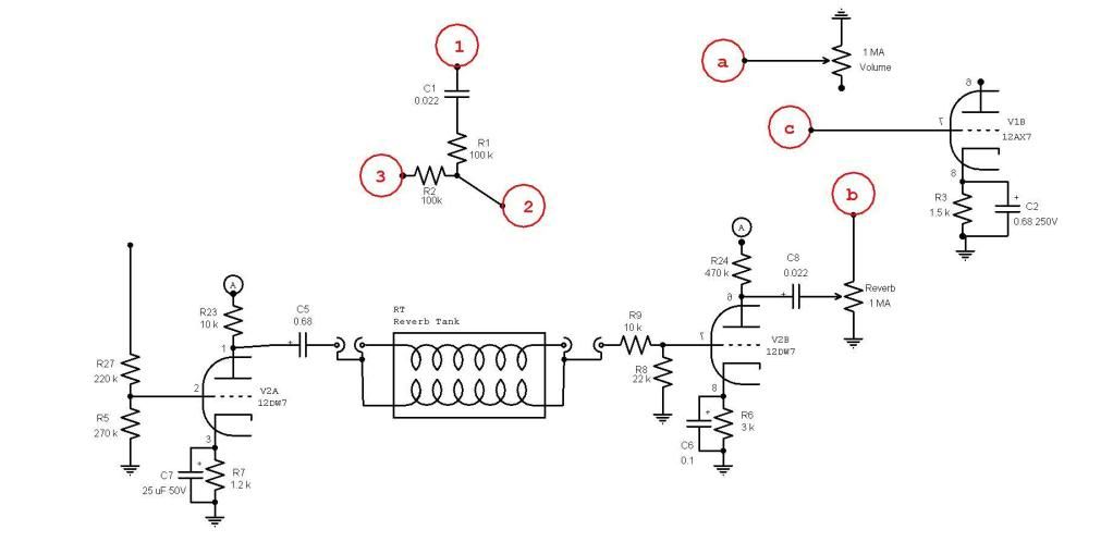
    Hi all, I have been working on a project amp with some success. I have everything working properly except my reverb! This is an idea used by Swart, and I tried to get the same effect. The circuit is Gibson Scout all the way except with modern tubes essentially. The tank is high impedance 8FB3C1C and it is cap-coupled.

    Currently I have dry signal only but if I tap the reverb tank, the 'splashing' sound comes through the speaker which leads me to believe there is either phase cancellation or some other problem with the driver/send (ie. the 12AU side).

    Does anyone have any advice? I have come up empty at some other forums and I took the amp to 2 techs in my town who were stumped.

    Thanks!


  • #2
    If that schematic is a literal representation of how your reverb tank is connected, that's your problem right there! There's a coil on the send end which needs to be referenced to ground as does the coil on the receive side. I'm going to guess that you do have it connected correctly though and that's just a drawing error- but I don't want to risk overlooking the obvious.

    Measure the signal going to the drive coil side of the tank. Verify that the input impedance of the tank you bought is correct for your driver circuit. Trace the signal and find out where you're losing it. I can't believe that two techs can't find the problem. It's elementary signal tracing.

    Nthan

    Comment


    • #3
      Thanks Octal.
      I can say for sure that the tank is not connected like the drawing. I think the RCA jacks make it pretty foolproof, no? Do you have any idea what I should be reading at the reverb tank input? The impedances should be fine as it is an Ampeg-style cap coupled design which uses an Accutronics 4FB tank. 8FB is just the short spring version.

      At the risk of sounding like a newb, can you tell me how to trace the signal? By reading mA?

      This is definitely a lousy town for tube amp techs!

      Comment


      • #4
        Signal tracing- the best way to do it is with a sinewave generator and an oscilloscope.
        You feed a sinewave signal into the input of the amp and check various points in the circuit- working forwards from the input or backwards from the output to see where you're losing signal.

        Since you're a newb, I would advise connecting scope probes to the points you're trying to test with the amp OFF. Power it up and then take your measurements. High voltage can be dangerous....

        Given that you're getting (loud?) output when you tap the tank, you can be pretty sure that everything is ok on the "recovery" end. My first port of call would be to check for signal at the plate of V2A. If you're not seeing signal driving the tank, then check the grid of V2A for signal.

        In lieu of an oscillosope and a sinewave generator, you can use a portable CD player with a test disc and a digital multimeter set to measure AC volts.

        Check the input/drive coil of the reverb tank for continuity. They can and do open up electrically. Also check for physical damage. They can get pretty messed up in shipping.

        Good luck
        Nathan

        Comment


        • #5
          Lets get some voltage readings from the power supply points A, B, and C. While you're at it, record the plate voltages in the amp to make sure everything is functioning properly.

          The drive side (12AU) needs to pump some current so point A is out. Point B would be better. You would like to see 300V or so. The 10K resistor on the plate needs to be at least a 2W part. From the 12AU7 curves, I would shoot for 10mA which needs roughly 6V of bias. So 6V/.01A=600 ohms, that's what the cathode bias resistor needs to be. 560 or 620 will do. That will give you about 100V across the 10K plate resistor. The 220K/270K voltage divider on the input of the driver tube acts like a volume control. If you need more drive, short out the 220K. The plate voltage of the first preamp tube could be a little low with the 220K plate resistor and 1.2K on the cathode. You should increase the cathode resistor to 2.2K to increase the headroom.
          WARNING! Musical Instrument amplifiers contain lethal voltages and can retain them even when unplugged. Refer service to qualified personnel.
          REMEMBER: Everybody knows that smokin' ain't allowed in school !

          Comment


          • #6
            Thanks very much, guys! I took some Voltage readings at lunch:

            A: 227
            B: 393
            C: 405
            'D' (first cap): 415
            V1a Plate: 87.7, Cathode: 0.851
            V1b Plate: 140, Cathode: 1.29
            V2a Plate: 167, Cathode: 6.65
            V2b Plate: 80.4, Cathode: 0.91
            V3a Plate: 120-220 (tremolo), Cathode: 1.12-1.69
            V3b Plate: 187
            V4,5 Cathode: 29.2

            Tonight I'll try and trace the signal. Are these in the right ballpark?

            I'm thinking V2a looks way off and taking B+ from point B may be too high??

            Comment


            • #7
              If you get no reverb at all when the volume pot is all the way down, there has to be a wiring mistake, bad or wrong component or a missing solder connection. It might be a better idea to fix that first before you try my suggestions. I don't see anything in the voltages that would prevent the reverb from working, at least a little. The voltage at point A is low, but that would just make the amp sound kind of dark, some people like that.

              Voltages are a little higher than I guessed they'd be. If the driver is moved to point B, the voltage on point B will drop 5 to 10V. But point A will probably increase to 300V. Leave the 1.2K in the cathode of the driver tube and it should bias up near 10mA, that's 12V on the cathode. You don't want the bias current to be any higher than 10mA, increase the cathode resistor if the current is too high. V1a plate voltage is on the low side, might cause the guitar's pots to be scratchy. Like a said before, increase the cathode resistor to 2.2K or so.
              WARNING! Musical Instrument amplifiers contain lethal voltages and can retain them even when unplugged. Refer service to qualified personnel.
              REMEMBER: Everybody knows that smokin' ain't allowed in school !

              Comment


              • #8
                Natman I am having difficulty reading many of the values on your posted schematic. However I have been working on a transformerless 12DW7 reverb for a while, and have got some questions/suggestions for your circuit. They won't explain why it's not working atm though!

                First up, you have no coupling cap for your reverb take-off, normally you have a low value cap to provide a high pass filter to prevent too much bass overloading the reverb tank.
                The voltage divider on the reverb driver grid may or may not be the correct attenuation to prevent overloading this stage, in the trial stages I would recommend using a 500k pot instead, and adjusting to your prefered value. This pot is called a "dwell" control, but if you find the resistance values that work best you can then sub in fixed resistors to replace the pot.
                As mentioned above, both of the reverb tank coils should have one side referenced to ground.
                The resistor grid lead and grid stopper for your reverb recovery stage are configured as a voltage divider, you will get more signal to the stage if you put the grid stopper after the grid leak.
                Also, I don't understand why there is a second coupling cap following the reverb control pot?

                Comment


                • #9
                  I have had another look at your driver stage setup. I think that I read your plate resistor as 10K, and above you stated your A voltage as 225V. Plotting a load line, your 0V DC point is 28mA, but with a 1.9K reverb tank in parallel, your 0V AC point is 175mA (parallel AC Z = 1.6K). Centre bias is ~ -7V, and your AC load line most definitely crosses the Wa (max power dissipation) line at ~ -1V.
                  I guess the point i'm trying to make is - is this a good way/best way to setup this stage? I'm used to thinking about voltage gain in triode stages, and not current gain, but this is running very close to, or even over max dissipation, and with an extremely steep load line. Is there a better way?

                  Comment


                  • #10
                    Most of the Ampeg amps which use this type circuit use a 6CG7 or 6SN7 driver - off the top of my head, those tubes have a bit higher allowable plate dissipation than a 12AU7 type tube but are otherwise very similar. Having said that, exceeding the Wa by a bit isn't why the OP's reverb doesn't work, so it's probably not worth worrying about now. If he has room for an extra socket, he could do a 6CG7 or double up the sections of a 12AU7 and then use a separate 12AX7 for recovery....


                    Nathan

                    Comment


                    • #11
                      OK, there's a wiring mistake here somewhere! Sorry for all the confusion, but I just realized that my schematic is not only wrong, but I have a couple of possible ways to wire up 3 connections. Being a newb, I'm not sure what would be right. I know the reverb circuit is virtually free of errors because it follows the Gibson Scout up to the output. FWIW this is a portion of an amp that I copied but wires ran under the circuit board and were not clear. I took a guess and this is probably where I went wrong. It's the triode where the reverb gets blended back in and the combined signal goes on to phase inverter (ie. V1b).

                      Can you suggest which connections go where? Have a look at this diagram if you please. I need to connect 1/2/3 with a/b/c. There are no other ways to connect the 3, no other wires in or out! The rest of the circuit is the same. Thank you SO MUCH!!

                      Last edited by Natman; 12-06-2010, 05:56 PM.

                      Comment


                      • #12
                        C1 is pretty much redundant, so I'd eliminate (jumper) it. Point 2 should go to "C" , points 1 & 3 will be identical with C1 removed so either one can go to points A & B.

                        Have you checked your drive signal on the send side of the tank yet?

                        Nathan

                        Comment


                        • #13
                          I set my guitar flat and put an ebow on the strings to get a signal going and these were my readings:

                          V2B Plate: 79 DCV
                          V2A Plate: 165 DCV
                          0.590 ACV at reverb input (I did notice some oscillation)

                          Basically the way I have those 3 connections wired is what you suggested. I jumpered the cap in case it was canceling phase, no dice.

                          I know that the circuit is supposed to use a 8FB3A1B (input & output grounded) and I have a 8FB3C1C (input insulated, output grounded). Could that cause a problem?

                          BTW, you guys have been a LOT more help than any other online resource for me. I want to thank you deeply.

                          Comment


                          • #14
                            Happy to help as time permits.

                            I looked at an Ampeg schematic and you've got R9 and R8 connected incorrectly. R8 should be connected from the output of the tank to ground. (it's the load resistor for the tank) R9 (a grid stopper) goes from that point to the grid of V2b. As you've got it set up, it's a voltage divider and you're throwing away a lot of your reverb signal there. I don't think it's your primary problem, but you should fix it before going further with the troubleshooting.

                            That drive to the tank seems quite low for a high impedance tank. It's hard to say without knowing the AC voltages in the other stages. I'm guessing (let me emphasize that this is a guess) that you'd want to see maybe 10V AC drive to the tank.

                            What AC voltage are you seeing on the grid of v2A?

                            Nathan

                            Comment


                            • #15
                              Maybe the tank itself is bad. Have you tested it in another amp? Do you have access to a known good replacement tank?

                              Have you tried running a guitar directly into the reverb recovery side? This will absolutely confirm the recovery side is working and eliminate it from worry.

                              It might be possible to drive another amp's tank while the tank is in the other amp to test the drive circuit, but this is risky.

                              A safer test might be to grab a pair of cheap computer speakers or headphones and hook them to the reverb driver RCA out.
                              Last edited by dchang0; 12-11-2010, 07:58 PM.

                              Comment

                              Working...
                              X