 Tweet
Tweet
Hello all,
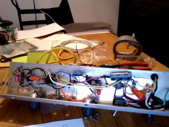
I'm rebuilding a Silvertone 1481. I have replaced all the resistors and capacitors with new parts (not the electrolytics but they're not leaking) and all the tubes. I also installed an 8" Jensen 4ohm speaker and a Heyboer hy022905M OT.
The OT came with red and blue leads on one side and green and black leads on the other. Several websites suggest that the blue lead is plate lead (AC hot) and red is the B+ signal from the 6v6. Green and black are the speaker leads. This is my first amp build. Is the 6V6 not enough tube to drive the 4ohm OT?
All the tubes are lit up and I know it's not a signal problem because the speaker does NOTHING. No speaker hiss.
http://www.freeinfosociety.com/elect...ertone1481.pdf
If my color coding is right, I'm wired exactly as the schematic describes. I'm going crazy and the girlfriend has just about had her fill. Thanks.
Paul
Comment