Announcement

Collapse
No announcement yet.

Follow Noob: Step-by-Step Building Winder

Collapse
X
 
  • Filter
  • Time
  • Show
Clear All
new posts

  • Follow Noob: Step-by-Step Building Winder

    OK guys. This is gunna be a step-by-step follow of how I'm building my sewing machine motor winder. It may take a little while as I'm moving this week... and then may be slow to build after that. But eventually it should have what you guys wanna see.
    Let's start with a parts list and where I'm getting them (subject to change/addition as needed below hahaha).
    Amazon:
    3/8" OD drill rod
    3/8" Spyroflo miniature housed bearings
    eBay:
    Cub3
    ~7000RPM sewing machine motor
    Grainger:
    4" 3/8" fixed bore sheave
    3/8" ID collar
    1/4" ID collar x2
    on/off/on DPDT switch
    HomeDepot:
    1/4" aluminum rod
    Lutron D-600P dimmer switch
    Mouser: (all parts based on classic amplification's schematic for 9v power source)
    828-OPB380T11Z optek optical sensor
    512-LM7809ACT regulator
    271-15K-RC 15kOhm resistor
    271-383-RC 383ohm resistor
    563-HH-3449 9V battery clip

    Chris

  • #2
    That looks like a good list of stuff. I have a few comments for consideration (I in no way claim to be an expert, just some things I came across on my quest to build a machine as well...)

    1) I'm assuming that you have a business license, or at least work under a licensed business??? Otherwise, you won't be allowed to shop at Grainger. They only sell to other businesses and this is something that I ran into when I tried to buy from them as well.

    2) As far as the counter goes, just be sure you know EXACTLY what you're getting with the CUB3. Know that it is not backlit, and the display is VERY small. If you want a nice red LED display, then I highly recommend the Red Lion APLT series. I just got an 0600 and it is really really nice.

    3) This kind of goes hand in hand with the counter, but do keep in mind that if you use a battery pack to power your sensor, you will need to unplug and replug every time, and when the battery starts getting low on juice, your sensor will become much less accurate, and even without you noticing until it's too late. The APLT sensors are powered via 120V AC and also have a terminal for a V+. It sends out 12volts, and so you can just put together a very simple circuit to step it down to where the sensor needs it to be. Mine is similar to yours, so i think it's somewhere around 1.7V or something like that to power the emitter side. So basically what you get from a counter with a V+ terminal is that you don't have to have a separate power supply from a battery or whatever, plus whenever your counter is on, your optical switch is on, and whenever you turn it off, the switch is off as well. There are quite a few features on the APLT counters, and I think you can program it to have an auto shut-off at a certain point, so it can kill the motor on your winder at a certain point, but this is only if you have a CNC winder or wired somehow that it would do that. My main reasoning for getting a higher-end one, is that if I ever build a better winder, I can just use the same counter and sensor, and it will do anything I want it to. Here's one on ebay right now: RED LION APLT0600 6 DIGIT LED TOTALIZER 115VAC REFURBIS - eBay (item 360178115799 end time Mar-30-11 18:59:09 PDT)

    I hope this can be of some help to you!

    Comment


    • #3
      Sadly, I've already purchased the counter. It's sitting right next to me. However, from a lot of the videos I've watched I like the idea of having an adjustable neck lamp to shine correctly to see really well where the wire is laying down. So I don't think the backlit thing will be an issue. As for the sensor. I have heard about the 9v battery being an issue. However, it's what I ordered so I'm going to give it a go. It won't be the end of the word to replace the battery clip with a DC power female plug and run it off one of the plethora of 9v DC power wall warts hanging around here.
      I was in Grainger just the other day and they didn't even mention it? She was more than willing to put in an order for me (I just hadn't figured out all the parts I needed yet). That said, it's good to know, I'll go back to THAT ONE hahahaha.
      That said, that's some great info to include for those that come along after me!
      Chris

      Comment


      • #4
        OK, so here's some progress on the build. I found some time to start work on the housings for everything. Here is a side view of my plans, I'll explain what you're looking at below:

        OK, so the two big circles in the top right are the 4" pulley from the parts list and then the larger circle is the CD that will trigger the optical sensor. In the center are the pillowblock bearings for the 3/8" drive shaft. Then of course to the left we have the motor and it's mounting bracket.
        I'm using 3/4" ply for all of this unless otherwise stated.
        Excluding the angled section cut out from the side pieces, they measure 4.3x6.7". The left edge is 1.5" tall. I wanted the thin to be 10" wide, so for the front/back pieces you need one piece 1.5x8.5" (8.5" long because with two pieces of 3/4" ply on either side this'll make my 10" width). The front piece is then 4.3x8.5". I used a 16x16" base for the machine and it seems like I'll have enough room. I then glued and nailed everything together.


        For those wondering what the slot in the front panel is for, it's to create enough space for the spinning CD that triggers the optical sensor.
        Next build a little 45degree angle housing (don't glue it down!) where the "face" is only 1/8" thick ply. You can't have it too thick or the knob for your dimmer switch won't reach through. I also cut out the space for the counter here. If you have a motor-reverse switch, this would be the place to put it too. Also, be sure to drill a hole big enough for the wires and stuff to go through to reach this housing.

        For the electronics, follow this diagram/pdf from Classic Amplification's website: Wiring Schematic
        I have already wired mine up with the exact parts listed in the parts list and it does work exactly as it should. Hopefully that will save some noobs searching for correct parts (and bugging the mouser people) for a long time like I did.
        More to come.
        Chris

        Comment


        • #5
          verhoevenc, Nice start. How will the motor mount? I've just started a new winder and am not sure how I will mount the motor. I'm going to try a reed switch for my counter, but if it can't keep up I may try the one you referenced. Thanks! Dan
          Last edited by Danelectron; 03-29-2011, 12:08 AM. Reason: punctuation. I know, but I'm ocd.

          Comment


          • #6
            Alright, not that much new to see this weekend... but stuff definitely got done.

            This is what the front section looks like with the dimmer and counter installed.

            Here you can see how I had to mount the photo sensor to get it up higher enough for the CD (see later) to pass through it and run the counter. The fact they have the wires come out of the bottom of it is a pain in the butt.
            I will add one more thing. I got the whole shaft/bearing assembly done and mounted as well this weekend... man was that a pain. SO, note to followers, 3/8" rod doesn't fit in 3/8" bearings. You need rod ever so slightly smaller (should have seen this coming). WHERE you go about getting that is beyond me cause I sure as heck didn't see it. SO, while I did some other stuff on the winder my friend spent a good bit of time with some sandpaper and oil sanding off a couple thou' until the rod would slide through the bearings. GAH! That was annoying!
            More to come,
            Chris

            Comment


            • #7
              I bet you were surprised how small the cub 3 is , I'm still using one as well .... but it works
              "UP here in the Canada we shoot things we don't understand"

              Comment


              • #8
                Yeah, the Cub3 is pretty small. Smaller than I was expecting. That said, I have every confidence it'll work just fine for me. With a well-lit shop it's size and lack of backlight should be ok.
                Chris

                Comment


                • #9
                  If you need lighting
                  you might need one of these
                  2 LED Clip-on Reading Light: Amazon.ca: Home & Garden
                  it helped me
                  "UP here in the Canada we shoot things we don't understand"

                  Comment


                  • #10
                    For those curious, my order on Grainger.com went through just fine. Just put my "Guitar Company" down as my company, didn't need a federal ID, nothin'. Got the parts today.
                    Chris

                    Comment


                    • #11
                      Hey verhoevenc, I plan to build something very similar to your build. I am going to use the same counter and switch/ power supply. I see where and how you positioned your switch, but I cannot really see how you wired it up. Could you post a picture of your wiring or post a drawing or something? I am completely clueless when it comes to electronics. Thanks man

                      Rob

                      Comment


                      • #12
                        Hey LesPau123, if you look at post #4 there is a link to the schematic. Use the parts listed in post #1 with that drawing and it will run off 9volts. If you want a different voltage to run it off, you'll have to do the math and what not listed on the schematic.
                        OK, so we are finally done here and I need to mention a couple problems I ran into! Here are the pictures of the finished winder:

                        The above shows the first problem I ran into. The see-through CD that I had was just too floppy and a little warped so it was spinning and hitting the photo sensor. So I had to ditch that idea and I made my own (MUCH) smaller lexan disc. Smaller means less floppy 
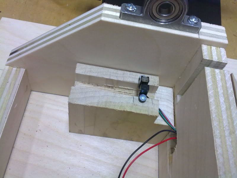
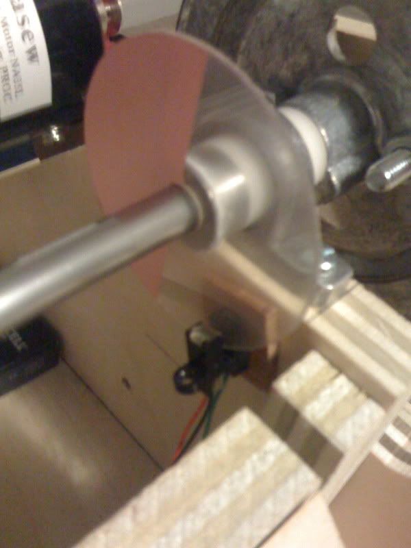
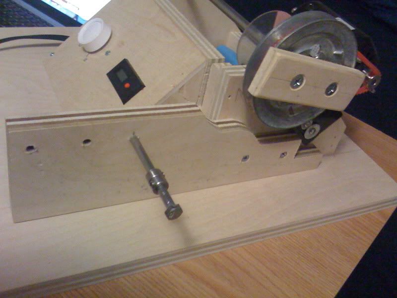
It's 2.5" diameter and is super-glued to a 3/8" collar so that I can ock it down to spin with the shaft (works like a charm; be sure you scuff up the side of the collar with 120 grit paper before gluing to help adhesion to the metal). Also, this meant that my original mounting of the sensor had to change... drastically cause one of the screws got strips and I had to cut off that side's mounting tab. As you can see I've simply super-glued (after making 100% sure it worked right) it to the right place.
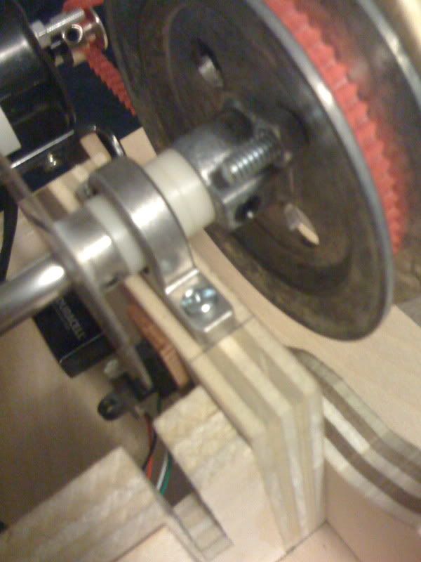
                        The above is the next issue I ran into. I figured lining up the motor pulley and the drive pulley would make things stay put... not so much! The shaft kept moving outward, making the drive pulley farther and farther from the housing as it ran. So, I had to lock things down and in place with some spacers and the disc's collar.

                        Lastly, since I've never wound before and don't have a great idea of how far the traverse should be from the pickup, I made this little non-permanent attachment with several options that I can try by simply unscrewing and moving the 1/4" bolt.
                        I will say... all said and done... this cost a bit more than I thought it was going to (the small stuff ends up adding up) and took a good deal longer than I was hoping too. I will say this... if I saw a used sewing machine motor winder on eBay for $250 or less... in hindsight, I'd buy it and save myself the work and purchasing of parts! That said, I still would not buy a Schatten or SideWinder with the dinky motors, etc. over building one like this.
                        Hope this helps some folks out and if you have any questions, I'm around!
                        Chris

                        Comment


                        • #13
                          Now the fun begins! Looks good.

                          Comment


                          • #14
                            So here are my first two bobbins:

                            Didn't break a single time! So I'm happy about that aspect. I will say though, that keeping a good "coil shape" is harder than one would imagine! The first bobbin (screw side, 5218 winds) is a LITTLE fatter at the bottom, but is kinda "lumpy", then the second wind (slug side, 5015) ended up (as you can see in the pic) a great deal fatter near the bottom. But the weird part is it's not the same on the other side. The coil is sort of like a parallelogram??? Weird. But it's my first, I'm sure I'll learn (advise welcome to get better shape) and I'm feeling these bobbins will WORK just fine and be a fun initial test.
                            Chris
                            PS: I wound to a speed that "felt good"... well I just clocked that speed out. I was winding at just over 900RPM. I've now marked there (925 to be exact) and where the knob goes for 600RPM as well. Could this have something to do with the shape? The next I'll try at 600RPM maybe? That said, I'm a little surprised at how close 600 and 925 are on the knob...?

                            Comment


                            • #15
                              Chris, The (mis)shape may have to do with how the wraps lay over the start lead. I've tried a few different methods to get the wire to lay uniformly flat across the bobbin as it builds over the start lead, and usually end up lagging at certain points to fill in the voids. They look nice for a first run. Fire 'em up and give us a review.

                              P.S. Got my new winder up and running and just tested the counter last night. Speed control is SCHWEEEET!

                              Comment

                              Working...
                              X