Announcement

Collapse
No announcement yet.

How to connect my Roland Synth?

Collapse
X
 
  • Filter
  • Time
  • Show
Clear All
new posts

  • How to connect my Roland Synth?


    This schematic shows an example of 3 Rolands (D20) Synth switches of C, E and G. This circuit exist 12 times for the 12 different tunes of an octave.
    As you see, each Roland key switch has two switches. The Roland Synth uses conductive material as switch to soften transients (like in PC-keyboards!)
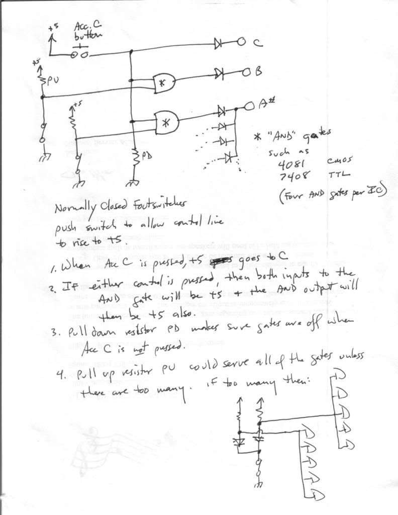
    Question: I need to connect these switches to a 120-button accordion accompaniment. When I press the accordion's C-major button these three tunes should sound at the same time, forming the c-major chord.
    What's the simplest way of doing this?
    Can I just use diodes and directly connect to Roland key switches?
    Or use two transistors per Roland key switch?
    Or have I to use 4066B?
    Last edited by jjj; 04-04-2007, 01:30 AM.

  • #2
    jjj, I just typed out a huge response and my computer just blanked it.

    Briefly, the Roland key circuit is a matrix. None of the things are grounded or brought to +5. You cannot operate the keys by grounding and pulling to +5. You must connect a row to a column in the matrix. An optoisolator at each key would work. That would be a lot of them.

    Roland uses a soft material for the contact so it will flex with the key motion. If a real switch was used, it would snap on and off, and be useless. There are two switches per key so the thing can sense velocity. One switch closes slightly before the other, and the computer can then from that calculate the speed of the key.
    Education is what you're left with after you have forgotten what you have learned.

    Comment


    • #3
      Thx Enzo,
      and my computer just blanked it.
      It's frustrating... drives me bananas, too!
      Briefly, the Roland key circuit is a matrix. None of the things are grounded or brought to +5. You cannot operate the keys by grounding and pulling to +5. You must connect a row to a column in the matrix. An optoisolator at each key would work.
      I successfully controlled the Roland switches via 4066B. I only thought there might be a simpler way, such as using two transistors to switch the two Roland key switches. In fact, I need only to connect 2 octaves.
      Roland uses a soft material for the contact so it will flex with the key motion. If a real switch was used, it would snap on and off, and be useless.
      In the olden days they used thin silver coils (I still got many of them). Yet to get rid of switching transients (of sine waves) the soft contact material is better or use 1nF to earth.
      There are two switches per key so the thing can sense velocity. One switch closes slightly before the other, and the computer can then from that calculate the speed of the key. Yes, I saw that and have got the service manual. I wired the connections for two octaves, incl. +5V & ground from the Synth into a socket outside the Synth. All ready!
      All I need now, is to know what best to do. 48 opto's is for two octaves...
      What about transistors or 4066B from which I have got heaps?

      Comment


      • #4
        In the old days, the silver springs and gold contacts were switching right in the sound circuits. These are digital control circuits, there are no sine waves to switch.

        4066 would work, just wire each gate section as a switch across an open switch on the Roland. The added bonus is that the control voltages and such can be kept separate from the Roland's. Transistors would be clumsy since they wouldn't refer to ground, at least in my view.

        I am still not clear, are you just going to have the notes of the scale with a master minor/7th control? Or are you planning to retain the minor and 7th buttons of the accordion? In other words three buttons for each note? More parts for the multibutton but simpler.

        Each button would feed a bunch of diodes that controlled whatever keys you want. One button for a major and one for a minor, and they don't really have to be related.

        A master minor and 7th control - one switch for each that worked for the entire octaves - would be a lot harder to implement.

        A MIDI accordion would solve the whole problem.

        Your accordion will not have dual switches - no velocity - so you can eliminate half those right now. The second switch that hits will usually give max velocity when struck alone. Try that, then you can switch only 24 if it works.

        SO with 4066s, from the C key, run diodes to the gates on teh 4066 for the C, E, and G circuits. Then the Cm button sends diodes to the vates for C, Eb, and G.

        I could not follow your original hand drawn circuit, it looked like some gates were wired to connect two notes together rather than turn two notes on at the same time.
        Education is what you're left with after you have forgotten what you have learned.

        Comment


        • #5
          Hi Enzo,
          Thx for your kind advice.
          In the old days, the silver springs and gold contacts were switching right in the sound circuits. These are digital control circuits, there are no sine waves to switch. True! So, there are no transient or contact bounce to worry about.
          4066 would work...
          Yes, I was thinking there's no easier way...
          I am still not clear... master minor/7th ...retain the minor and 7th buttons ...three buttons for each note?
          Nothing of the sorts! Each accordion button has only one contact and I just connect each chord button via diodes and 3x 4066B to the Synth keys; to 12 keys from the lowest octave for major bass an terz and 12 keys from midle of next octave for chords. My idea was to wire e.g. accodion chord button C via a diode to C,E,G blocks (12 such blocks). From there I than wire them to the 4066B gates (i.e. 3 x 4066B for chords and 3 x 4066B for bass & terz)

          Your accordion will not have dual switches - no velocity - so you can eliminate half those right now. The second switch that hits will usually give max velocity when struck alone. Try that, then you can switch only 24 if it works. Closing one alone of the two Synth key switches won't work. The only other way is to create one switch (from the two Synth switches) is, by connecting e.g. at C-chord G via diode and H via diode together and this held onto 8 creates a switch and it worked! At first I was worried that this might interfer with the Synth keyboard's velocity, but no it didn't. Beside, I invented a kind of wrapping method/ tool (a siringe tube with sanded endings connected to an empty yarn coil), which feeds 0.09mm polyurethane (Philips) copperwire. (I got 2kg of it!) With that I just 'wrap up' all connections and directly solder them, burning off isolation. 100's of channeled wires take amazingly little space! I can show you a photo of some 40 IC's (4066) connected this way... if you insist.
          SO with 4066s, from the C key, run diodes to the gates on the 4066 for the C, E, and G circuits. Then the Cm button sends diodes to the gates for C, Eb, and G.
          Yes, that's the way. I already prepared the chord charts and numbered every diode connects (13 diodes each in each block; 12 blocks of it for chords only) so, I find faults faster, later on.
          I could not follow your original hand drawn circuit, it looked like some gates were wired to connect two notes together rather than turn two notes on at the same time.


          That was this circuit, which I want to connect to it as well. This circuit connects two 'odd' notes together, because I only use it, to control Live-Styler (Yamaha-Styles) accompaniment software, which requires momentarily to press the next black key to the left to switch to MINOR or a white key to the left to switch to 7th accompaniment mode. I still need some help on that (values of resistors?) or I have to do trial & error...
          One question to above circuit: This circuit will be needed 12 times. To control this circuit via foot switch, I will have to connect all earthing resistors together. To separate them eletronically I'll need to insert diodes. Since it's to earth the cathodes have to be on the foot switch side... or?

          I translated the Live-Styler's manual (Ger-Eng) and the owner gave me a free copy of his software. On his pages I also left an instruction of how to convert a Synth keybd. to JANKO!!! http://www.live-styler.de/home/Janko%20Project.pdf Together with the accordion accompaniment I'll have the easiest to learn & play Synth in the world! Check it out!
          How to reward you? Chances are you like my talent, since I like yours? My electronic knowledge only consists of observations, suffered shocks and burned parts...
          How to reward you? Chances are you like my talent, since I like yours? http://www.live-styler.de/home/images/jjj-DEMO.wma That's me twittering, there! I can also pay credit to your help in my Janko project PDF and mention this forum's name, for I don't believe in 'free meals'...
          Last edited by jjj; 04-05-2007, 03:12 AM.

          Comment


          • #6
            I am still not clear... master minor/7th ...retain the minor and 7th buttons ...three buttons for each note?
            Nothing of the sorts! Each accordion button has only one contact
            You misunderstand my question. On the accordion, the left hand for each note of the scale has a major, a minor, a 7th, and I forget what else. How many contacts under it are not part of my question. Limiting myself to minor and 7th then, each note of the scale would have three buttons for major minor and 7th. is this what you are doing?

            OR

            each not of the scale has just one button, and if you want minor or 7th, you would press a footswitch. That footswitch would convert the bitton closure from Major to either minor or 7th as selected.

            SO my question remains: for ONE octave of this, are there 12 buttons and a two switch footswitch. Or are there 36 buttons? Accordion style would have the 36 buttons. But some electronic ones have side switches on the expression pedal for minor and 7th.

            The drawn circuit I couldn't figure was not that one, I meant the one with 4066s. In some cases it appeared that certain gates connected two notes together, as if C# were on one pin and D on the other.

            Let me ask this a different way. I am assuming the "C" accordion button is the one in the array at the left hand, yes? Where are the minor and 7th buttons located? FOotswitch? On the accordion?

            Now then, do we have two different things going on? It seems like at one point we are trying to make the Roland play chords from one button via hard wired interconnections. And then you seem ALSO to want to make the encoded key inputs to tell the accompaniment circuits what to do.

            Again, in the drawing just above, WHERE are the A# B and C connections? They cannot be to the Roland key circuit. Are they to gates on the 4066?
            Education is what you're left with after you have forgotten what you have learned.

            Comment


            • #7
              Hi Enzo,

              Limiting myself to minor and 7th then, each note of the scale would have three buttons for major minor and 7th. is this what you are doing?
              There are 120 buttons on the accordion left hand part from old, electronic Farfisa accordion... (The rest of the accordion isn't there anymore, for I only use the 120 button box!) There are:
              20 buttons for terz bass, one tune ea.
              20 buttons for major bass, one tune ea.
              20 buttons for major chords, 3 tunes ea.
              20 buttons for minor chords, 3 tunes ea.
              20 button for 7th chords, 4 tunes ea.
              20buttons for Dim chords, 3 tunes ea.
              Each button (of the 120 buttons) has only one contact. Of course, to make chords, I need to to wire e.g. accodion chord button C via a diode to C,E,G blocks (12 such blocks). From there I than wire them to the 4066B gates (i.e. 3 x 4066B for chords and 3 x 4066B for bass & terz)
              Is that what you needed to know?

              SO my question remains: for ONE octave of this, are there 12 buttons and a two switch footswitch.
              The circuit with the foot switch has nothing to do with the connection of the 120 buttons to the Synth.
              The foot switch circuit serves only to control Live-Styler (Yamaha-Styles) accompaniment software (via the accordion button box as well!), which requires momentarily to press the next black key to the left to switch to MINOR or a white key to the left to switch to 7th accompaniment mode.

              The drawn circuit I couldn't figure was not that one, I meant the one with 4066s.
              Originally I thought to control that Live-Styler software with 4066 via the footpedal, but then I got into problems, because when I press the foot pedal all gates were flolating, causing a chorus... so, I worked out the above shown foot pedal circuit, which seems to be less complicated and better.

              I am assuming the "C" accordion button is the one in the array at the left hand, yes? The C row consit of:
              E-terz bass,
              C-bass,
              c-major chord
              c-minor chord
              c-7th chord
              c- diminined chord
              Where are the minor and 7th buttons located?
              http://www.accordionpage.com/basar.html

              FOotswitch? On the accordion?
              Will be on the floor near my foot.

              Now then, do we have two different things going on? It seems like at one point we are trying to make the Roland play chords from one button via hard wired interconnections. And then you seem ALSO to want to make the encoded key inputs to tell the accompaniment circuits what to do.
              That's right, they are two different circuits and jobs. I like to control Live-Styler software via the 120 buttons pentasonic accordion box, because then I can play any melody without thinking of chord notes (instinctively!), just as I do with the Janko keyboard. To play both (the 120 accordion buttons and the Janko keyboard) I need only to learn one pattern in the major scale and one pattern of minor scale in order to be able all 24 scales (of major & minor!!!) Which other instrument offers us that? Non!

              Again, in the drawing just above, WHERE are the A# B and C connections? They cannot be to the Roland key circuit. Are they to gates on the 4066?
              Exactly! This circuit I want to add after the accordion button box is connected to the Synth. I guess the value of resistors is hard to predict and so, I better try it out myself using two 2-5K Pot's to find out how high the resistance of both resistors can be to safely earth the +5V and not to load the Synth's +5V PS.
              One more question to above circuit: This circuit will be needed 12 times. To control this circuit via foot switch, I will have to connect all earthing resistors together. To separate them eletronically I'll need to insert diodes. Since it's to earth the cathodes have to be on the foot switch side, isn't it...or?

              Yes, keep asking, because these things are pretty tricky. I think by now you got all info...
              Last edited by jjj; 04-05-2007, 03:21 AM.

              Comment


              • #8
                I don't see how this wil be reliable. You can't have pull down AND pull up resistors easily. Look at the 4066 again. You mentioned gates floating. You must terminate all gates.

                Look at the first gate in the 4066 pins 1 and 2 are switched tohether or open depending upon gate pin 13. +5 on pin 13 and the pins 1 and 2 are connectde together - the switch is ON. Ground pin 13 and switch 1-2 is open, that is not connected together. The four gates in each chip are identical, it doesn't matter which one you use for what. I will use pins 1 and 2 here just for example.

                Look at your footswitch. Keep the diodes. Erase the resistors. Now accordion button C - I am now going to start calling that Cab - Cab when pressed sends +5 to C. SO far, OK. Now replace the horizontal resistors with a switch from a 4066. Eliminate the vertical resistor. Now run a pullup resistor - 10k maybe - from +5 direct to the gate of the switch in the minor path to A#. Wire a second pullup from +5 to the gate of the switch in the 7th path to B.

                At this point we have Cab turning on C and because of the pullups to their gates, the minot and 7th paths are also at +5.

                Now all you have to do is connect the minor switch to the bottom end of the resistor to the gate in the path to A#, and connect the 7th switch to the bottom end of the resistor to the gate in the path to B.

                SO the gates of the 4066 switches are ON unless turned off by the footswitch. The way we make that practical is that we use the NORMALLY CLOSED type switch on the footswitch. That keeps the gate grounded - OFF - until you step on the footswitch. That is exactly what you wanted.

                Any faults in that theory?

                You can wire all the minor gates together, and you can wire all the 7th gates together. They can all open and close all they want, their associated keyboard control will only see +5 of its associated accordion button is pressed.
                Education is what you're left with after you have forgotten what you have learned.

                Comment


                • #9
                  Hi Enzo,
                  From afternoon until almost 11 P.M. (Chile time) I couldn't get into your forum; did you have maintenance? I rang my ISP (VTR) and they too couldn't get in. Now back to work...
                  From what I gather... you describe the foot switch circuit I proposed before drawing up this simple 2 resistor circuit, which you say is unreliable, because I can't have pull down AND pull up resistors easily.
                  Here's the previous foot switch circuit with 4066B:

                  Note: Here I only show the complete connection of accordion button C.
                  Each gate (ins 5, 6, 12, 13) has a 22K pulldown resistor to ground.
                  There are 2 groups ( group Minor IC1 to IC3) and group 7th IC4 to IC6)

                  Pressing accordion button C sends +5V to SW pin 4 of IC1 and when I press Minor foot switch +5V are send to all gates of IC1 to IC3
                  Result: I only wanted to have C and a# activated by pressing button C and Minor foot switch. Yet, since the footswitch sends +5V to all Minor gates I get a chorus of all switches on from IC1 to IC3, instead!
                  I mentioned 'gates floating'... because, the only way to stop the chorus would be to earth the other gates... or have 24 foot switches (for Minor & 7th) under the table!
                  See, the problem is that I need to control either group via a foot switch.
                  Whereas the simple foot switch circuit with the 2 resistors allows to effectively earth out unwanted voltages to 4066 gates. I cannot imagine that this would be a problem, for there are only minimal currents involved. The same is done with voltage dividers. Thus, it's easy to override one or the other. For as long the resistor's values are kept high enough it won't load the PS, either. Crucial is that the unwanted gates remain closed if they are earthed via the foot switch.
                  Last edited by jjj; 04-06-2007, 04:02 AM.

                  Comment


                  • #10
                    Not quite. In the drawing with resistors, you have a diode in ALL THREE lines - C, B, A#. In the 4066 drawing, I don't see the diodes to the natural note, C in the example.

                    I am drawing up a different approach. Let me figure out how to upload the drawing and I will return. I want to ditch the 4066 and use logic gates.
                    Education is what you're left with after you have forgotten what you have learned.

                    Comment


                    • #11
                      Hi Enzo,

                      It's 1 A.M. in here, but I like to quickly add (before I got to bed...):
                      Not quite. In the drawing with resistors, you have a diode in ALL THREE lines - C, B, A#. In the 4066 drawing, I don't see the diodes to the natural note, C in the example.
                      That's correct, too! But it is, because I only wanted to show the 3 situations.
                      Normally the C is already connected to 4066 (= the first part of two of my project!) Tomorrow more! Good night... sleep well!

                      Comment


                      • #12


                        See if that makes sense.
                        Education is what you're left with after you have forgotten what you have learned.

                        Comment


                        • #13
                          Hi Enzo,

                          Yes, yes, you got it right! Did you not sleep last night? The trouble with me is that I mostly learned electronics from practical experiences... and know electronics is in me. I wished I had a friend like you...here; then we could enjoy lots of happy days! I have good ideas, only need friends to help solving them!

                          Well, I seem to completely understand your AND foot switch circuit. Why didn't you immediately think of it? (Sorry, my fault for not letting you know all details...) I don't know a thing about AND/OR, NOR, NAND etc. gates, I only heard of their 'existence'.
                          The PD-resistor effectively grounds unwanted currents. So, to control all 2x 12 of these circuits I would need only to add diodes into its control lines.
                          Yes, perfect... what more can I say, than offer you a big hug and thank you for your good thinking! The pleasure is ours!
                          You see I too enjoy helping people in need in my musical and philosophical abilities. Wouldn't it be nice if all people in this world would just help each other and so, help themselves minimizing suffering? What a shame our world is still such a savage place...
                          By the way this idea of mine, of building the easiest to learn & play instrument, is quite revolutionary... I like to think, or? I played the piano accordion for years by ear and so, learnt to appreciate the circle of fifths accompaniment. That made me think that a similar should be also possible with the melody keys. Almost a 100 year ago, Janko, the Hungarian mathematician, worked it out! Now a Japanese firm took it up and created a Synth with a Janko- keyboard, but is only available in Japan. My musical friend in FL/USA is desperate to buy one.
                          The advantages are such that it’s simply the easiest to learn & play MIDI instrument in the world! What more one you ask for?
                          Things can be even easier by using the 120-bass buttons box from a mechanical, old accordion. There you got all chords ready. Press the 7th button and you see 4 levers moving! All it then needs is to add switches to drive 3 x 4066 for bass & and 3 x 4066 for chords.
                          Last edited by jjj; 04-06-2007, 05:02 PM.

                          Comment


                          • #14
                            Now the details: So, I still would need PU resistors and at what value?

                            Important: The +5V for the And gates PS have to be connected after the button SW!

                            When accordion button C is activated only C goes to 4066 and then to Synth SW, because foot SW is (normally) closed and the +5V from the button are earthed out via PU resistor and PD resistor so, no current flows to AND gate!
                            Whereas, when accordion button C is activated and one of the foot switches opened +5V flows to (either A# or B) AND gate and then to 4066 etc. so, that I will hear two tunes.

                            On a second thought...
                            Now that I see that and gates work similar to 4066 gates I ask myself... maybe my whole project can be done with AND gates? Unless there's nothing gained? Jeez, I was glad you 'kicked me' to rethink how to control the Synth's key switches via one switch, because now I need only half of IC's and wiring /work. That's why I'm all for simplicity!
                            Last edited by jjj; 04-07-2007, 01:01 AM.

                            Comment


                            • #15
                              I sleep days, I work at night. My online time is breaks. When I do my own projects I usually go right straight to logic. In your case I started out trying to help you fix what you already thought of. I decidede after a time that it would be better if I started anew.

                              If you leave the input of a logic gate unterminated, it can float to some random voltage and assume an unpredicatble logic level at the output. There must be pullups or pulldowns or another logic output tied to each input.

                              I would not try to have one master PD and diodes, I would just use 12 of them.

                              Logic gates are simple. There are AND and OR - AND is the rounded one and OR is the more pointed one. There are more complex versions, but most have two inputs. Call those A and B. and also an output X. Each point has two possible states: high and low. You might call it on and off, +5 or ground, 1 or 0, but high and low is the common term. +5 is high and ground is low.

                              Everything then is an if/then statement. AND: If A AND B are both high, THEN the X is high. It takes both inputs high to get the output high. If either one (or both) is low, then the output will be low.

                              OR: If A OR B is high, then X will be high. It only takes one of the inputs high to make the X high. If one is high, then it doesn't matter what the other does, since one is sufficient. BOTH A and B must be low to get X low.

                              Those are the gates. And there is one more logic operator: the invert. This device takes an input and makes the output the opposite. Input high makes output low. Input low makes output high.

                              Add an invert after an AND gate, and it becomes a NAND gate. Same for OR, it becomes NOR.

                              From these three things you can make all logic.
                              Education is what you're left with after you have forgotten what you have learned.

                              Comment

                              Working...
                              X