Announcement

Collapse
No announcement yet.

I Messed up my Fender Stage 112SE

Collapse
X
 
  • Filter
  • Time
  • Show
Clear All
new posts

  • I Messed up my Fender Stage 112SE

    I've got a Fender Stage 112SE that I've had since new (1996). I've never had it opened up/modded/repaired until recently. I just replaced the clean channel volume pot with an audio taper pot. While I was in there, I touched up a few cracked/sketchy solder joints.

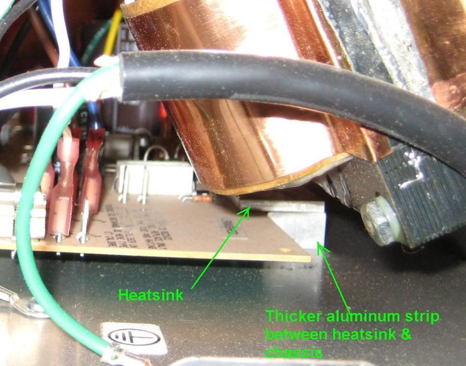
    Before I mounted the chassis back in the cab, I turned it on to make sure everything worked OK. I hadn't yet connected the external speaker jack back up yet. I also hadn't reinstalled all the screws (only 2/7) that attach the back of the board, through the thick aluminum strip (heatsink) , to the chassis. The amp turned on fine, so I plugged my guitar in just to check if it played fine. It did. There was a slight "shhhhh" static noise as it sit there with the guitar plugged in, but got silent when the guitar cable was removed. I thought this may me due to the external speaker jack not being connected, so I stuck it in its hole and the amp made a pop noise (similar to touching the end of a guitar cable while it's plugged into an amp) so I pulled it back out and left it alone.

    Then, I decided, I would check for any loose components while the amp was on by lightly touching (with a plastic mechanical pencil) some caps, resistors and diodes on the side to see if any seemed loose and made noise. I got some slight noise from a few, but then I would touch the same one again and would get nothing. Then I apparently touched the wrong thing because the fuse blew, and I smelled a slight burning smell coming from somewhere.

    I pulled the board back out to check for any obvious damage, but visually found none. I went and got some more fuses at Radio Shack. I re-assembled the amp completely and replaced the fuse, I turned it on. I was greeted by a hum for a split second before the fuse blew in a flash of greenish light. I double-checked all my connections and tried again. Same thing. Then I thought I may have connected my RCA cables to the reverb pan wrong, so I reversed them. Fuse still blew.

    Now I am at a loss. I pulled the board out again to look for damage, scorch marks, anything out of the ordinary. I couldn't find anything.

    I have the schematic and a digital multimeter, but I'm not sure where to start with the troubleshooting.

    Thanks,
    Mike

  • #2
    Welcome to the place. It sounds like one of your output transistors has shorted. If your meter has a diode check function use it to check the output transistors. If your meter doesn't have a diode check function, use the ohm meter instead.

    The outputs are the large plastic cased blocks that are mounted to the aluminum heatsink. Each one has three legs. Viewed from the top the legs are from left to right base, collector, emitter. The most common fault is a short from collector to emitter. Because the output transistors are paralleled, if one is shorted, both on that side will test as being shorted.

    If the transistors test ok, then the next thing to check would be the power supply diodes for shorts.

    Let us know what you find out.

    Comment


    • #3
      Originally posted by 52 Bill View Post
      Welcome to the place. It sounds like one of your output transistors has shorted. If your meter has a diode check function use it to check the output transistors. If your meter doesn't have a diode check function, use the ohm meter instead.

      The outputs are the large plastic cased blocks that are mounted to the aluminum heatsink. Each one has three legs. Viewed from the top the legs are from left to right base, collector, emitter. The most common fault is a short from collector to emitter. Because the output transistors are paralleled, if one is shorted, both on that side will test as being shorted.

      If the transistors test ok, then the next thing to check would be the power supply diodes for shorts.

      Let us know what you find out.
      My meter does have a diode test function.

      The transistors are the black components labeled tip142 or tip147 at the top of this photo, right?
      http://i37.photobucket.com/albums/e9...hsd/amp009.jpg

      I'm assuming the diodes I need to test are CR13-16?

      Do I need to remove the components from the board to test them?

      Comment


      • #4
        I did some quick probing at lunch. Hope you can understand the way I formatted the results.

        All 3 TIP142 transistors read the same. 2nd value is with the tester leads reversed

        B-C - .68, .50
        B-E - .68, .50
        C-E - 0, 0

        All 3 TIP147 transistors read the same

        B-C - .49, .63
        B-E - .49, .63
        C-E - 0, 0


        Here are the readings from some of the diodes:

        CR 37-40 - .54, 0L

        CR41 - .85, .60

        CR42 - .84, .54

        CR34&35 - .451, .457

        CR33&36 - .480, .443

        CR13-16 - .45, 0L

        Comment


        • #5
          The zero readings from C-E on both sides is what I suggested as being the most common fault when these transistors short out. But my guess will be that only one on each side, one 147 and one 142 will actually be shorted. In order to find out if this is true or not, you will need to remove them from the board.

          What I do in these cases, is to use a solder sucker to remove the solder from the Collector lead of one transistor. Now I test that transistor from C to E. If it shows a short (zero on the meter) I will remove it completely. If it doesn't read as shorted, I then remove the solder from the Collector of the next transistor in line and retest that transistor. This way I only remove the bad transistors for further testing. The good ones only need to have their Collector resoldered to finish testing the power amp circuit.

          Do you have or know about a light bulb limiter? You will probably find it helpful to finish the repairs of your amp if you have one. Basically it puts an incandescent light bulb in series with the amp circuit to limit the current that can pass through the amp that you are working on. This will usually save any additional parts from being destroyed if there are still problems with the amp when you power it up again.

          Comment


          • #6
            Originally posted by 52 Bill View Post
            Do you have or know about a light bulb limiter? You will probably find it helpful to finish the repairs of your amp if you have one. Basically it puts an incandescent light bulb in series with the amp circuit to limit the current that can pass through the amp that you are working on. This will usually save any additional parts from being destroyed if there are still problems with the amp when you power it up again.
            I read in another thread about the light bulb limiter but wasn't sure so I googled it. I found this site that instructions on how to make one: Light Bulb Current Limiter
            Is this what I need?

            I'll do some more testing on those transistors tonight. Thanks for your help so far.

            Mike

            Comment


            • #7
              Originally posted by woodardhsd View Post
              I read in another thread about the light bulb limiter but wasn't sure so I googled it. I found this site that instructions on how to make one: Light Bulb Current Limiter
              Is this what I need?
              Yes, that will work just fine.
              My Builds:
              5E3 Deluxe Build
              5F1 Champ Build
              6G15 Reverb Unit Build

              Comment


              • #8
                What I do in these cases, is to use a solder sucker to remove the solder from the Collector lead of one transistor.
                Agree and add.
                I would not only suck dry the collector pad, but would also lift slightly the collector leg, say, 1mm above the board, to make *sure* it's not still touching the pad.
                After testing you reinsert it and resolder, if good, or pull it fully and replace it with a fresh one if bad.
                Remember to use grease and mica, as it was before.
                Juan Manuel Fahey

                Comment


                • #9
                  Originally posted by J M Fahey View Post
                  Agree and add.
                  I would not only suck dry the collector pad, but would also lift slightly the collector leg, say, 1mm above the board, to make *sure* it's not still touching the pad.
                  That was an awesome tip. My solder sucker bulb couldn't quite get all the solder off so even though the pad was dry, there was still continuity.

                  It appears like I only have 2 bad transistors, Q8(TIP142), and Q5(TIP147), the two middle ones. Here are my readings:

                  Q8 - 0, 0
                  Q7 - .476, 0L
                  Q6 - .469, 0L

                  Q5 - 0, 0
                  Q4 - .427, 0L
                  Q3 - .431, 0L

                  Now, which TIP142 and TIP147's do I get to replace these? I saw on mouser that there are about 4 different kinds of each. I see TIP147, TIP147G, TIP147U, and TIP147TTU

                  Originally posted by J M Fahey View Post
                  Remember to use grease and mica, as it was before.
                  Pardon my ignorance, but where can I find this mica, and what kind of grease?

                  Comment


                  • #10
                    A TIP147 is a TIP147, but they sometimes come in 2 sizes. There is a "small" TO220 case, not recommended. The one you want (it surely is specified in the Mouser page) is the "large" one (same as you have now), the case may be called TO218 (the one with a metal flange as seen from the front), it requires mica and a nylon bushing ; or TO247, which as seen from the front is almost all plastic, the hole already is plastic on the inside and does not need a bushing.(it's built in).
                    Both cases, of course, have a metallic back, the side that faces the aluminum heat sink.
                    To keep it electrically insulated, you insert between transistor back and heatsink a thin rectangular strip of mica.
                    Ask for one that matches a TO218/TO247. Buy a dozen, they are cheap and for safety must be discarded if you pull a transistor, even if it's fine and gets to be remounted later.
                    To better transmit heat, both sides of said mica are slightly covered with a thin layer of "Thermal grease", buy a preloaded syringe or a small pot.
                    There are some so called "Sil Pads", insulators made out of a special rubber which avoids thermal grease (and messyness).
                    Personally I much prefer traditional mica and grease, others do not.
                    Anyway try to reproduce what Fender made.
                    The screw or bolt which goes through the transistor hole will short it to the heatsink, so you need to use an approppriate nylon bushing to insulate it.
                    TO247 transistors don't need it, so if you can choose, go for them.
                    Good luck.
                    Juan Manuel Fahey

                    Comment


                    • #11
                      Alright, I found these on Mouser's site.


                      TIP147 STMicroelectronics Darlington Transistors

                      TIP142 STMicroelectronics Darlington Transistors

                      _

                      As far as the mica: I found some keystone brand mica pads on mouser for the TO220, but they appear to be a little to small for the TO247

                      There was also these:
                      A15038-002 Laird Technologies / Thermal Solutions Thermal Interface Products
                      "Tgard™ 500 is a medium thermal performance insulator pad consisting of a ceramic filled high temperature silicone rubber coated on electrical grade fiberglass."

                      I'm assuming these are the "sil pads" that don't require the grease.

                      Last, I saw these:

                      43-77-20G Aavid Thermalloy Thermal Interface Products
                      Thermalfilm™ and Thermalfilm™MT are low cost polymide plastic insulating films designed to be an improved replacement for mica. These insulators have a distinctive amber color and can be easily recognised and assembled on a production line

                      I'm assuming that these are just a mica substitute and need grease, correct?

                      Basically, I need the most idiot-proof product.

                      Comment


                      • #12
                        The glassic one I suggested is 56-02-101G (universal type TO218/247) in this datasheet Standard Products - Insulators - Mica but they are out of stock.
                        In the yellow material they have: 43-77-20G Aavid Thermalloy Thermal Interface Products
                        which will do nicely.
                        It needs grease (you spread a little with a toothpick, both sides, so it oozes out a little when you tighten your screw).
                        Those TO247 transistor cases will let you avoid insulating bushes, one thing less to worry about.
                        Good luck.
                        Juan Manuel Fahey

                        Comment


                        • #13
                          Originally posted by J M Fahey View Post
                          The glassic one I suggested is 56-02-101G (universal type TO218/247) in this datasheet Standard Products - Insulators - Mica but they are out of stock.
                          In the yellow material they have: 43-77-20G Aavid Thermalloy Thermal Interface Products
                          which will do nicely.
                          It needs grease (you spread a little with a toothpick, both sides, so it oozes out a little when you tighten your screw).
                          Those TO247 transistor cases will let you avoid insulating bushes, one thing less to worry about.
                          Good luck.
                          OK, I'll order those.

                          Last question, which grease do I need? There is a thicker aluminum strip that sits between the heatsink and the bottom of the amp chassis. I noticed it has a bit of grease on it. Do I need to grease between the heatsink and this thicker piece? Here is a photo showing what I'm talking about:


                          Just kidding, another question. Some of the results on the diodes I tested indicated (to me, at least) that some are bad. CR33-36 are testing OK, now, but CR41 and CR42 are still testing bad.

                          Thanks again!

                          Comment


                          • #14
                            You are doing well.
                            That grease is available from Mouser, they probably refer to it as "thermal grease" or "thermal transfer paste".
                            It's used between mating surfaces, to fill the tiny spaces which are inevitable.
                            After replacing transistors and diodes (also check ceramic resistors ) turn it on, no speaker attached, and *always* through the lamp limiter.
                            Check that is turns on normal, you have all rail voltages and you do not have DC voltage on t speaker output (50mV, less than 100mV DC is acceptable)
                            Juan Manuel Fahey

                            Comment


                            • #15
                              It has been pointed out that you need insulating mica washers or equivalent. But what happened to the ones already in there? When you remove the transistors from the heat sink, the old mica washers generally either stick to the heatsink, or they come away with the transistor. They stick because of the tacky heat grease. Unless you destroyed them, they are usually reused.
                              Education is what you're left with after you have forgotten what you have learned.

                              Comment

                              Working...
                              X