Announcement

Collapse
No announcement yet.

Circuits involve active electronics and a dummy coil.

Collapse
X
 
  • Filter
  • Time
  • Show
Clear All
new posts

  • #31
    I'm considering this for a two pickup RW/RP guitar, which necessitates invertering the coil for one of the pickups. My question is - I understand that the follower described above adequately buffers the dummy, but what about the inverting leg of a single transitor phase inverter? It's much higher impeadance, right?

    Consider this:


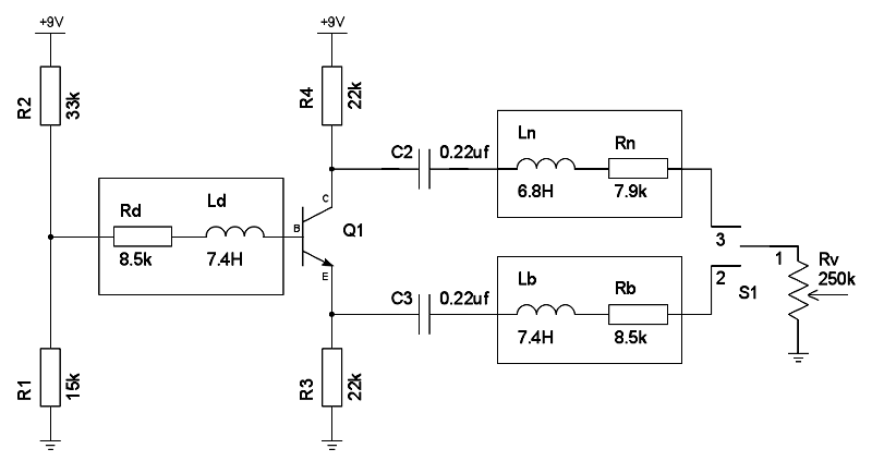
    The boxes are pickups, I slapped in values from a similar pickup. And what about leaving the big honking inductor that is a pickup flapping in the breeze when it's not in circuit? In a passive guitar circuit, they do no harm, but here you've got the end of an inductor that's AC coupled on one end into a circuit thats still functioning.
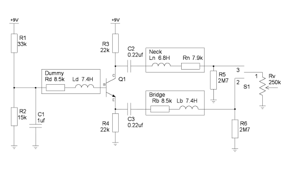
    The prince and the count always insist on tubes being healthy before they're broken

    Comment


    • #32
      Nate,

      I like it! Try it!

      The impedance of your transistor circuit will be minute compared to your pickups impedance.

      You might also consider a means to "balance" the Hum generated by the dummy with the Hum generated by the pickups.

      Maybe experiment with capacitively bypassing the Bias network. Technically, an LR is formed by R1||R2 +Rd... Possibly completely inconsequential.

      Nice work, good luck!
      Ethan

      Comment


      • #33
        I considered putting in balance but decided against it for a couple reasons. First off, the dummy coil is going to be another GFS Mean 90 that I rip apart and put just the coil in the space between the neck and bridge pickups. So it will be exactly matched with the bridge pickup, and nearly exactly matched with the neck. (Which btw, the RW/RP both pickups on position cancels very well.) Second, this guitar is a top routed strat, with a pickguard and 24 fret overhang (it's a Warmoth 24.75" scale conversion neck, so the overhang is about the same as a 22 fret neck). You can tweak for hum balance with the pickguard out, but once it goes together, I do not want it drifting. The neck's already been off and back on more than I'd like getting electronics tweaked (it has a Graphtech Hexpander/Acoustiphonic also.)

        I considered (and drew up) an alternate where the neck and bridge pickups were DC coupled to the phase inverter (and thus have a DC path to ground always) - and to their individual emitter followers. But the Graphtech already buffers the magnetic output, and there is no tone control in the guitar, so the only benefit that has is in the location of the buffer.
        The prince and the count always insist on tubes being healthy before they're broken

        Comment


        • #34
          That makes sense.

          Does it have a middle position?

          Comment


          • #35
            Yes - it has a 3 way blade switch. The guitar is a schizophrenic combination of Luddite and High tech. It contains a Graphtech Ghost piezo saddle / 13 pin MIDI out, with P90's in a humbucker box, and minimalist controls. 3 way blade, and two volume knobs (three actually, magnetic and MIDI volume are stacked on the "volume" knob, the second "tone" knob is the summed Piezo volume, and contains a pull switch wired to the 'Dark' switch on the Acoustiphonic preamp. Magnetic & Piezo are always in 'blend' mode and manipulated by the volumes. If you're interested, you can find more over at the unofficialwarmoth forums. There's some finished pictures and a very long tortuous build thread.

            Minor edit: bypassed the bias divider, added DC path to ground on the high impeadance side of the pickups.


            Will the 2.7M to ground create a significant noise source? Since it's a 3 - way, maybe just putting it across the switch pins is enough to tame any pops, let the volume ground take care of things.
            The prince and the count always insist on tubes being healthy before they're broken

            Comment


            • #36
              Originally posted by NateS View Post
              I'm considering this for a two pickup RW/RP guitar, which necessitates invertering the coil for one of the pickups...
              Nate:
              IMO there is a simpler way to accomplish this without having to use electronic circuitry to invert the dummy coil- check out the wiring diagram for the Gibson Blueshawk:

              Click image for larger version

Name:	BHcircuit.jpg
Views:	1
Size:	42.9 KB
ID:	824175

              Click image for larger version

Name:	BH_wiring_update.jpg
Views:	1
Size:	149.7 KB
ID:	824176

              The first picture is the official Gibson wiring diagram while the second one was what the curator of the BluesHawk website drew up himself with some corrections made after he was finally able to obtain the official schematic. (Gibson ought to post his drawing since it is much easier to understand!) He goes into a lot more detail in his very excellent single-purpose website, which is undoubtedly everything you wanted to know about one of Gibson's most interesting guitars!

              www.blueshawk.info/resources

              I believe that the dummy coil used in the Blueshawk is basically a P-90 coil without the magnets or any kind of metal load. The BH selector switch has just 3 positions, all of which are humcancelling, so you don't get to A/B the effect of the dummy coil (which from my experiments adds some compression and loses some of the brightness.) It seems like most people think that it is the RW/RP properties that create the humcancelling effect but I figured out on my own strictly by accident that it was the [B]reverse winding[/B] that was responsible for the humcancelling effect and that the reverse polarity that keeps the pair in phase. I guess that is common knowledge now among guitar techs but I was shocked when I discovered that since the Brosnac book (1st edition) was my bible and he did not consider the possibility of a humcancelling pair that was out-of-phase (see the chart on Page 35 1st ed. which has a 4 x 4 grid showing all 16 combinations of strat pickups).

              In any case my interpretation of the drawing is that the two pickups are NW/RP with the windings of the neck pickup inverted in the middle switch position. The neck pickup is South up and the bridge pickup is North up, but all three positions of the selector switch are humcancelling (the dummy coil is bypassed in the middle position which is a series linkage.) It would be easy to add a switch (or a pole of a 4P/5T or 4P/6T switch) to bypass the dummy coil in the neck only or bridge only positions when humcancelling is not needed. (I think that Gibson left that option out to keep people from A/B-ing the effect of the dummy coil and discovering that it sounded better without it!) One more thing to note in the drawing- for the middle position of the switch the signal to the controls is shunted through a treble bleed RC network consisting of a 100k resistor and a 0.0047uF cap to brighten up the sound of the series linkage. You should be able to add a switch (or switch poles) to be able to get a parallel linkage in the middle position.

              Good luck!

              Steve Ahola


              EDIT I had drawn up a wiring diagram inspired by the BluesHawk which had a RW/RP pair of P-90's wiring in series with a dummy coil in the middle. The middle position would have the two P-90's in series- I forget if I was able to get them in parallel as well. I'll have to see what I can come up with again. (My LP Jr Special is just begging for a dummy coil between the two P-90's under the pick guard.)
              Last edited by Steve A.; 02-07-2012, 04:26 AM.
              The Blue Guitar
              www.blueguitar.org
              Some recordings:
              https://soundcloud.com/sssteeve/sets...e-blue-guitar/
              .

              Comment


              • #37
                That schematic makes the active circuit look simple. I'm glad to finally see that schematic though.

                There are two choices: 1) make the dummy coil an insignificant load 2) make the the dummy coil an insignificant load. Active electronics is actually the least technical way to do this. IMO

                Comment


                • #38
                  The Cap is actually a good idea. The bias network in series with the winding resistance creates a LR high pass... A few dB... But none the less, I like that you add it

                  The 2.7M are also wise! Good thinking. The 2.7M's are in parallel with your volume. Thermal noise will be shunt by the volume control. I'll check that link next time I jump on a computer. Thanks for sharing. I like your "hair brained" ideas

                  Comment


                  • #39
                    I'm new here, but recently did some work with a dummy coil on a Tele ... seems this is not a new idea to you all - but it was to me.
                    I have the whole story posted here with pictures, if you're interested.

                    https://sites.google.com/site/string...for-sc-pickups
                    “If you have integrity, nothing else matters. If you don't have integrity, nothing else matters.”
                    -Alan K. Simpson, U.S. Senator, Wyoming, 1979-97

                    Hofstadter's Law: It always takes longer than you expect, even when you take into account Hofstadter's Law.

                    https://sites.google.com/site/stringsandfrets/

                    Comment


                    • #40
                      Great article! I admire people who can explain things as well as this. I don't find your name anywhere on your site

                      one typo:
                      "....One is electromagnetic and this noise source is addressed by shielding. Again, there are lots of websites and articles about shielding. Ideally, a metal shield surrounds the guitar electronics, including the PUs, and is tied to the guitar cable ground...."

                      A conductive shield, such as foil, "shields" from the electric field, not the electromagnetic field.

                      By reading your article, I am quite certain that you know this and it is only typographic

                      Excellent job, I think you should sign your name to it!
                      Cheers,
                      Ethan

                      Comment


                      • #41
                        Originally posted by CRU JONES View Post
                        Great article! I admire people who can explain things as well as this. I don't find your name anywhere on your site

                        one typo:
                        "....One is electromagnetic and this noise source is addressed by shielding. Again, there are lots of websites and articles about shielding. Ideally, a metal shield surrounds the guitar electronics, including the PUs, and is tied to the guitar cable ground...."

                        A conductive shield, such as foil, "shields" from the electric field, not the electromagnetic field.

                        By reading your article, I am quite certain that you know this and it is only typographic

                        Excellent job, I think you should sign your name to it!
                        Cheers,
                        Ethan
                        Thanks Ethan - good catch - EM is not my strength so I used the terminology loosely. I've made the fix - and actually caught another in the process. Thanks again.

                        My site has my gmail address (uneumann@gmail.com) if anyone wants to reach me. As for signing, it seems like email is a sig these days. ;-)

                        -Ulrich Neumann
                        “If you have integrity, nothing else matters. If you don't have integrity, nothing else matters.”
                        -Alan K. Simpson, U.S. Senator, Wyoming, 1979-97

                        Hofstadter's Law: It always takes longer than you expect, even when you take into account Hofstadter's Law.

                        https://sites.google.com/site/stringsandfrets/

                        Comment


                        • #42
                          I've now made a hum cancelling coil for a strat-like guitar (my G&L S-500). It works great and it's pretty easy to do.
                          Details are at https://sites.google.com/site/string...for-sc-pickups
                          “If you have integrity, nothing else matters. If you don't have integrity, nothing else matters.”
                          -Alan K. Simpson, U.S. Senator, Wyoming, 1979-97

                          Hofstadter's Law: It always takes longer than you expect, even when you take into account Hofstadter's Law.

                          https://sites.google.com/site/stringsandfrets/

                          Comment


                          • #43
                            Att. Mike Sulzer.
                            Old thread but looking for answers :-)

                            I know my way around tubes but not much about transistors/fets etc.
                            Anyway I breadboard your dummy coil buffer circuit, testing several J201 i'm getting at the output (top of 27k resister) between 0.55v to 0.85v (Vdd is 8.6v).
                            Is that ok?
                            This means current drain is like 30nA...
                            I'm not getting any voltage reading on the gate... i guess its in nano-volts... shouldn't the gate be biased to some level like mid Vdd?

                            * post edit: guess i haven't built anything in a while... gate is at 0V while source is at 0.55-0.85V so its fine for mV noise signal :-)
                            I was just thrown off by googling jfet followers schematics and seeing them all being biased by a divider to mid Vdd.

                            Btw, if i'll use a gain stage (common source, which inverts the signal) before the buffer, with the dummy at same wind direction as the pickups, does it mean I'll also get some level of electrical noise cancellation?
                            Last edited by Amit; 10-15-2015, 11:34 AM.

                            Comment


                            • #44
                              I prefer the source follower in this application because of the low impedance looking back into it. (If you use the circuit for two pickups this provides isolation.) But the circuit with gain should work as you say. Also be careful with noise (hiss). If you use fewer turns on the dummy and amplify up, you might notice hiss.

                              I like the low current because battery life is long, and it works, but there is nothing wrong with changing the circuit for higher current with traditional biasing if you like.

                              Originally posted by Amit View Post
                              Att. Mike Sulzer.
                              Old thread but looking for answers :-)

                              I know my way around tubes but not much about transistors/fets etc.
                              Anyway I breadboard your dummy coil buffer circuit, testing several J201 i'm getting at the output (top of 27k resister) between 0.55v to 0.85v (Vdd is 8.6v).
                              Is that ok?
                              This means current drain is like 30nA...
                              I'm not getting any voltage reading on the gate... i guess its in nano-volts... shouldn't the gate be biased to some level like mid Vdd?

                              * post edit: guess i haven't built anything in a while... gate is at 0V while source is at 0.55-0.85V so its fine for mV noise signal :-)
                              I was just thrown off by googling jfet followers schematics and seeing them all being biased by a divider to mid Vdd.

                              Btw, if i'll use a gain stage (common source, which inverts the signal) before the buffer, with the dummy at same wind direction as the pickups, does it mean I'll also get some level of electrical noise cancellation?

                              Comment


                              • #45
                                Originally posted by uneumann View Post
                                I've now made a hum cancelling coil for a strat-like guitar (my G&L S-500). It works great and it's pretty easy to do.
                                Details are at https://sites.google.com/site/string...for-sc-pickups
                                I just checked out uneumann's link and found it to be interesting although it deals strictly with passive dummy coils...

                                I've attached a PDF capture of the page for future reference...

                                saf.dc.pdf

                                Steve A.
                                The Blue Guitar
                                www.blueguitar.org
                                Some recordings:
                                https://soundcloud.com/sssteeve/sets...e-blue-guitar/
                                .

                                Comment

                                Working...
                                X