The feedback resistor (by design) needs to be selected to match the gain of the output tubes and phase inverter. In guitar amp land- try different values till you find one you like!
so, if i understand correctly, i may need a higher value resistor for my 6550's to achieve the same nfb as say the avenger's 39k will with the 6l6's ...?
another thing i have become curious about after reading is how adjusting the PI plate resistors will affect tone in a couple respects.
1] ive read the aim is to stay within 10%-20% of each other, how is tone affected when we start to move outside this window, ie 100k and 100k,
or the other way 100k and 75 or 70k?
2] the larger resistor is determined by doubling the triode plate resistance. im looking at the data for an EH 12ax7 tube, it lists 54,1kohm.
so if i double this im at 110k for example.
what happens to tone when we move the values of both resistors higher, keeping the 10%-20% imballance.
sorry for the questions, the more i read the more curious i become!
Dear beinz.
Please don�t consider me rude, we want to help you, and anybody else on anything music/electronics related, but this Forum is not a replacement for proper Electronics education.
Your questions wander all over the place, and worst of all, seems that answering any of them is futile because after doing so, in good faith, you ask something absolutely unrelated dropping the former subject.
Also, many of them are so basic as to show lack of, well, basic understanding of Electronics.
Are we getting anywhere closer to any basic goal with all this? Is there any definite goal to be achieved?
Many of your questions "don�t have an exact answer" (sorry, can�t find a better way to express this) since there are many conflicting answers, all of them possible but depending on taste.
I mean widely differing answers.
How can you pick one without actually trying all of them?
Words often fail to describe properly subtle differences in sound.
You also quote entire paragraphs of Electronics books and ask us to explain them.
May I humbly suggest you read them 5/10/20 times until you "get" what they say?
Hint: that�s what most of us did .
And continue doing .... personally every time I re-read something I get something new.
Or reading comments by distinguished colleagues here I often have many "oh" moments, as in: "hey ! ... I hadn�t noticed that ! ... cool ! .... I hadn�t seen it that way !"
You want to design a high gain tube amp. Fine.
A mighty task, may I add, not an easy subject.
May I suggest you actually build one?
An already proven one to begin with, so as to minimize probable frustrations.
You mentioned Soldanos: cool.
Killer amps and a reference for anybody.
Even having the full schematic and even layout suggestions (there are a couple Forums dedicated specifically to that, such as SLO Clone Forum), it won�t be easy .
Yet I find it the practical path.
Meanwhile also read a lot.
*After* building it "by the book" and debugging it (it will provide *many* amusing afternoons, which will soon lead to *long* nights), start exoerimenting with , say,
>what will happen if PI plate load resistors are modified?
>what if NFB resistor is modified?
>what If I take NFB fom a different tap?
> what if I use another Power tube?
> what if .... ?
> what if .... ?
....................
> what if .... ?
and so on, endlessly.
Anywhere along the path, feel free to ask about any doubt, but doubts about things you have already tested and *heard*.
Suggestions can also be put into practice, accepted or discarded , your choice.
But as is, we look like a dog chasing its own tail.
understood, i apologize, your help certainly isnt futile, i probably do jump around alot, only because this build is a slow work in progress for me and i dont have the means to "build as i blog". i do not wish for you to explain sections i have read, although yes i certainly do not have a "great" understanding electronics, i was only only hoping for your experiences or opinions on certain topics. agreed the best method for some of my questions is to "try it and see/hear", as for actually building the amp, i couldn't agree more! this is the goal.
my apologies, just curious, but i guess i have more learning to do.
Dear beinz, you neednt apologize for anything, all your questions look inspired by a wish to know.
What I am afraid of, is that we are getting into an area which relies more on "opinion" and personal taste, and "conflicting" answers will make you more confused, rather than less.
There is something which you have not asked yet, which is a bigger problem than anything "electronic" (which, after all, can be modified at will), and I refer to what�s the most complex problem for the Home Builder: the chassis, which is a "mechanical" problem.
Since you want to experiment (excellent) I would try to get a somewhat oversized one (for space) with a couple extra Noval holes beyond what you already plan to use, and a few extra front and back panel holes, suitable for jacks, pots, and maybe a couple toggle switches.
And a nice oversized turret (or equivalent) board inside.
This way, you can build your PSU first, then a Power amp, then add a basic preamp, and after it�s working and playable, (and you *do* play through it), start modding at will, adding more stages, clean channel, tube loop, channel switching, you name it.
All along the way you will have a playable amp and be able to hear, at once, the effect of any Mod or new idea.
It will be *way* more fun, too .
Trying to get everything pre-solved, is almost impossible.
Even if everything works properly ... you might not like it
As an example, I remember Mesa�s Randall Smith said once, that they often built a rough chassis in the size they thought it would work, would put a piece of styrofoam inside and press into it all parts, in the approximate locations, *before* designing (and ordering) the actual PCB or the actual commercially fabricated chassis, to check that everything fit inside, certain critical parts weren't too close, etc.
He said they had to start doing so, after a couple "very expensive mistakes "
We are talking MESA BOOGIE here !!
Imagine any of us, mere Mortals
EDIT:
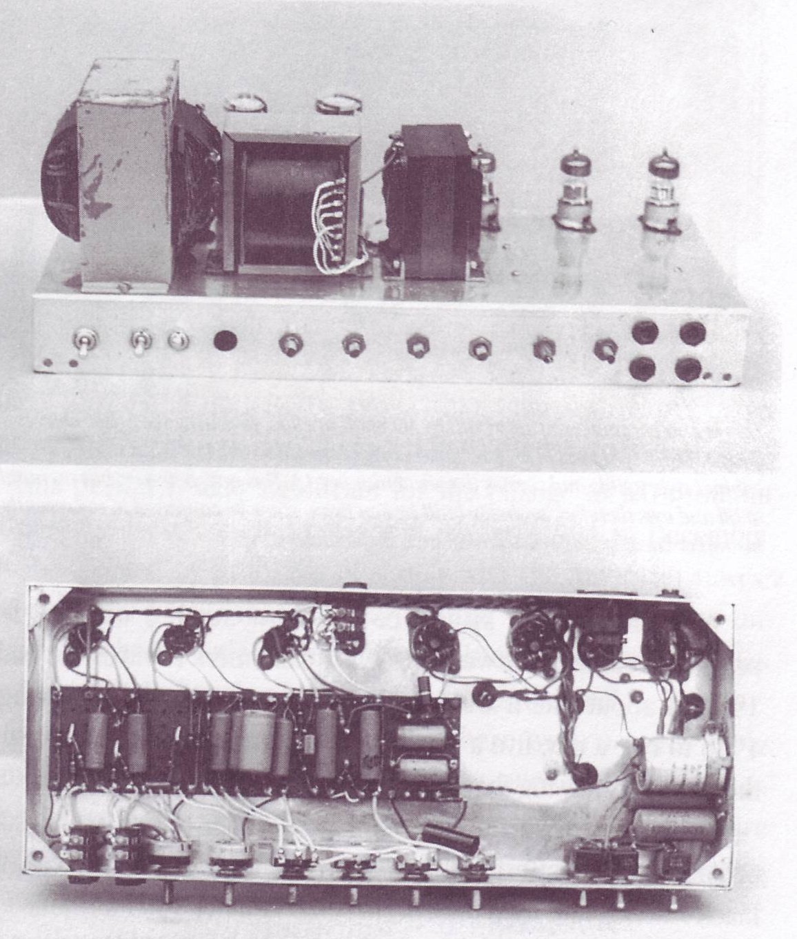
just to encourage you, have a look at Marshall's *sixth* prototype (he said he would be too embarrassed to show the first five, which, anyway, were "cannibalized" untill getting to this)
Not much in the way of cabinet, knobs, or panel markings (although Sharpie comes to the rescue)
As a side note, History (or Myth) says a certain neighbourhood kid, by the name of Ritchie Blackmore, visited the shop often and offered suggestions about its sound.
Not much Math or Theory but actual playing stuff.
Your posts have tended to focus on individual parts in many cases. One bit of philosophy I like to preach is this - it's the circuit, not the parts.
What that means is, for example, "the" feedback resistor is just part of the overall circuit. SO saying Marshall uses a 100k feedback resistor but Fender uses a 22k or whatever, overlooks that the resistor is part of a voltage divider circuit that feeds a portion of the output back into the phase inverter at some point. SO concerning over the value of that one resistor is like concerning over my weight by looking at only one digit of it. "Hey DOctor, one of the numbers in my weight is 4. How is my diet working?"
In that example, the output signal from one of the speaker leads is fed through "the" resistor, but ultimately finds another resistor from there to ground, and those two resistances make a divider, leaving that proportion of the output signal as the feedback. SO a 100k to a 1k resistor would be a 100/1 voltage divider, but so would a 47k and a 470 ohm resistor be.
Filter caps. You need a certain minimal amount to kill hum, in particular the first filter stages. But by the screen B+ node (node just means a point along the way), pretty much your hum (ripple) should be gone. The extra filter stages for the preamp sections are mainly about "decoupling." Look that up.
B+ starts high at the beginning, right out of the rectifier, say 500v for the power tube plates, then something close for the screens, say 485v. Maybe we only want 350 for the phase inverter, and 300 for the rest of the preamp. We do that by calculating the current draw of all the stages, then we use Ohm's Law to determine what resistance we need to drop the necessary voltage at those currents. SO when Marshall has two 50uf caps in parallel, that is just them making a 100uf cap, but if there is a resistor between the pins, then they are no longer in parallel, and that resistor is there to create a voltage drop. SO we can;t really compare a MArshall uses 10k between the caps while Fender uses something else until we add up the currents from the downstream tube stages and calculate the desired voltages.
WHy might Marshall use a 50x50/500 can instead of a 100uf/500 can? 100uf is 100uf, but they already use 50x50 cans all over their designs. If they went to a 100/500 can for this one spot, they'd have to add a new part to their inventory. That costs more money. SO they simply use the 50x50 cans that they stock by the thousands and wire the sections together. So their reasons are totally not involved with the circuit, it is just penny counting.
Education is what you're left with after you have forgotten what you have learned.
Perhaps a better move for now, as mentioned above, would be a prototyping chassis.
Get a generic 20 watt power transformer and output transformer. Drill holes across the front for a variety of controls, an input jack and power and standby switches. The back should have jacks for speaker outputs, a fuse and some sort of power input, usually an IEC connector on my amps. Get some JJ 6v6's as they're pretty forgiving of abuse. Drill/punch the chassis for two octal sockets and 3 or 4 noval (9 pin) sockets. Get a single chassis mount 50ufx2 can cap for your plate and screen filters and make a corresponding hole- that way you won't have to make room for them later. Plan to use cathode bias so you don't have to think about bias supplies for now. You can probably buy a generic "50 watt master volume" chassis that is already set up this way for the most part and make a few minor changes as needed.
Make a basic garolite or frp eyelet board with three rows of 30 eyelets on .2 or .25 inch centers. The rows should be an inch apart. Cut a similar sized piece of garolite or frp to go under the eyelet board as an insulator so you don't short things out on the chassis. Now you have a "tube breadboard" that you can use to experiment with whatever designs you want. At moderate volumes the power amp won't factor into the equation much. Since you're after a high gain design you can build preamps until you're comfortable and you'll have a prototyping chassis that can be easily used to try new designs with minimal hassle.
When you find a design you like, lay it out on graph paper with the entire chassis and all components represented in 1:1 or 1:2 scale and build yourself a new chassis. You can now create a turret or eyelet layout for a specific circuit rather than generic random stuff.
all great advice guys, thanks.
too many variables affecting other variables ...ect.
i do certainly want to get it as "right" as i can before i get started, but you are right, i have to just start with something proven, and work from there!
an easy workable chassis is a good place to start, then go from there.
Build a good basic Marshall, then go from there.
If you want high gain, the Marshall Platform is a good place to start.
T
"If Hitler invaded Hell, I would make at least a favourable reference of the Devil in the House of Commons." Winston Churchill
Terry
6550s and the variants tend to sound better at higher plate supplies. As used in Mar$halls with plate voltage intended for EL34s, they just don't "wake up" and sound pretty bland. Up around 600v should lively up the sound with plenty of output. Rich Koerner (co-designer of the GE 6550a) shares this thought.
The farmer takes a wife, the barber takes a pole....
 Tweet
Tweet
 .
. .
.

Comment