Announcement

Collapse
No announcement yet.

5E3 Volume Tone mod

Collapse
X
 
  • Filter
  • Time
  • Show
Clear All
new posts

  • 5E3 Volume Tone mod

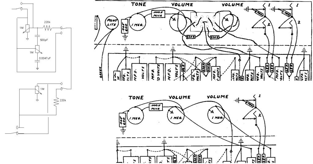
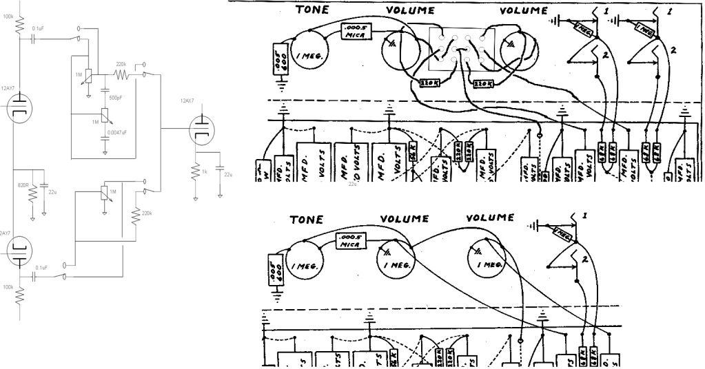
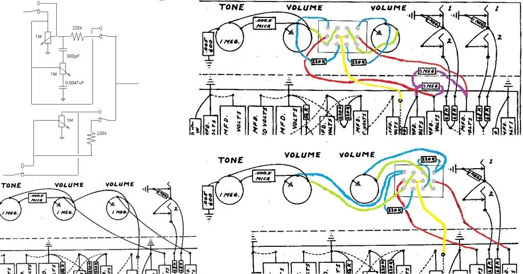
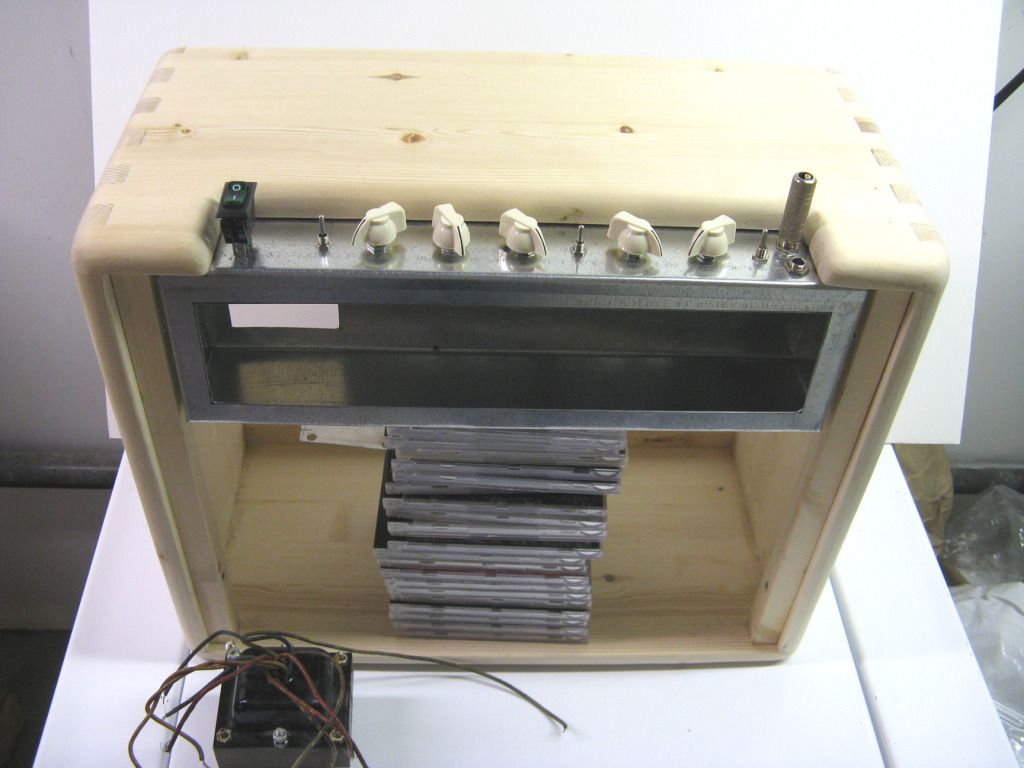
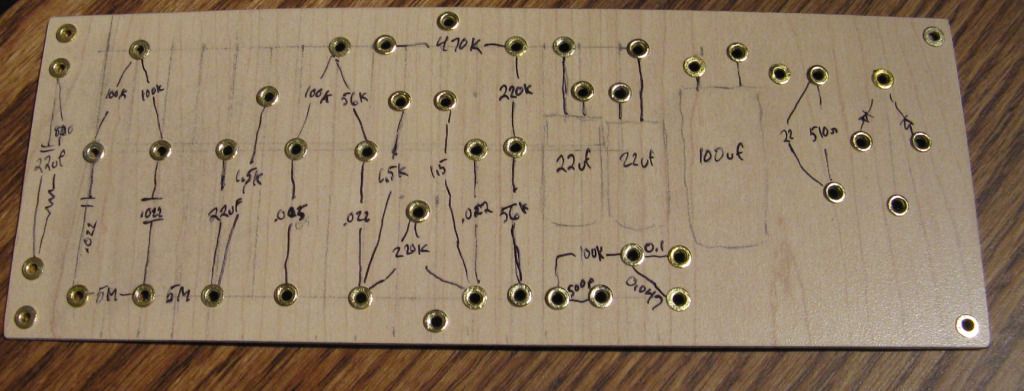
    I figured out how to change from the 5E3 interactive volume and tone controls to the normal voltage divider pot arrangement using a four pole toggle switch and a couple of mixing resistors. I figured out the reversing of the pots way back but I never thought to put the mixing resistors in the loop. So for any of you that wanted the stock 5E3 funky control response but would also like to change to the normal Brown circuit. A four pole toggle switch and two mixing resistors, schematic is in the normal position.


  • #2
    Well done.
    To ease understanding and implementation, as it's a 4 pole switch, the schematic should show all 4 poles in the same state; currently the top 2 are 'brown' and the bottom 2 are 'tweed'.
    It may be beneficial to add a high value resistor, eg 10M, between the grid of the 2nd stage and ground; without it, I assume that operating the switch makes a 'thump'?
    Pete
    My band:- http://www.youtube.com/user/RedwingBand

    Comment


    • #3
      Thanks.

      The top channel has the signal input going on top of the pot and through the wiper, 220k resistor, and then out the switch. The bottom channel has the signal also going through the top of the pot, through the wiper, then the 220k resistor then the switch.

      I thought about the switching and the pop, decided it would less confusing for people with little electronic experience to see what is going on without it. I drew up a layout using Paint and the original Fender drawing to make it easier for those that wanted to try it. I am not sure if there is enough clearance on a 5E3 chassis for the switch in this position, I usually make my own and space the controls for what I need.

      Comment


      • #4
        Originally posted by pdf64 View Post
        Well done.
        To ease understanding and implementation, as it's a 4 pole switch, the schematic should show all 4 poles in the same state; currently the top 2 are 'brown' and the bottom 2 are 'tweed'.
        It may be beneficial to add a high value resistor, eg 10M, between the grid of the 2nd stage and ground; without it, I assume that operating the switch makes a 'thump'?
        Pete
        Oh, I see what you mean, you want the switch toggle to be in the same direction. I am used to not concerning myself with the physical direction on a schematic and usually leave that for the layout. It sometimes makes the schematic easier to comprehend when you have a lot going on and you can keep the wire routing simpler. I'll see what I can do.


        How's this?

        Last edited by printer2; 10-08-2012, 02:10 PM.

        Comment


        • #5
          You might want to include the coupling caps "inside the loop". The 6G3 uses .02uF and 0.1uF might be too bassy. Might get a large thump when you throw the switch though.
          WARNING! Musical Instrument amplifiers contain lethal voltages and can retain them even when unplugged. Refer service to qualified personnel.
          REMEMBER: Everybody knows that smokin' ain't allowed in school !

          Comment


          • #6
            Hope this helps. Added 5M resistors on the downward side if the blocking caps in the top diagram. Colored the wires to see where they go better. Boy I really hate working in paint.

            Comment


            • #7
              So I have been kicking around this idea of changing from the 5E3 control arrangement to a normal Tweed-Brown controls for a while but this last go round came out of my Gibson BR-1 field coil amp project. I looked at the amp and realized it was sort of a Fender 5C3 (although cathode not grid biased) but with a pentode in front of one channel. So I did some modifications so I ended up with a Deluxe styled amp with a pentode option. Now I took thing a little further and drew up the switched 5E3 as above and rather than just a boring single volume second channel I stuck a Blackface tone control in the loop.

              So now I have 5E3 in one position and a Brown Princeton on the instrument channel along with a BF tone stack on the normal channel. Added a switch to go from NFB to no NFB to bypassed second stage just for kicks. I did want to do a 5E3-BF amp before, the one in the Build forum, and while I still would like to try that amp but this one is calling to me, might have to put aside the field coil amp also. Not sure what output tube I would want to use though, I have some 12L6's that would make a nice 10W amp.

              Comment


              • #8
                Not sure if I should start this again in the 5E3, or the Build forum or just continue on. Last night I worked on the chassis.


                Today I used Fender's layout and I made it mine.


                Cut and paste, and sloppy wiring. Should have use my own colors rather than continue with Fenders, live and learn.
                Last edited by printer2; 10-12-2012, 03:12 AM. Reason: updated layout

                Comment


                • #9
                  I don't see where the connection to chassis ground is made in your layout. If I may make a suggestion, run a ground wire from the preamp end of the board to one of the ground terminals on the input jacks.
                  WARNING! Musical Instrument amplifiers contain lethal voltages and can retain them even when unplugged. Refer service to qualified personnel.
                  REMEMBER: Everybody knows that smokin' ain't allowed in school !

                  Comment


                  • #10
                    Originally posted by loudthud View Post
                    I don't see where the connection to chassis ground is made in your layout. If I may make a suggestion, run a ground wire from the preamp end of the board to one of the ground terminals on the input jacks.
                    Still making changes, going to a single cathode and resistor on the input, only two input jacks but with a switch to go to one both or the other channel, repositioning a few things. I reminded myself to put the ground wire in for the jacks but promptly forgot. I usually tie them in at the first stage cathode-resistor node. My working drawing is a lot uglier due to the corrections, probably will not see the light of day till I have the amp up and running and everything worked out. My biggest concern is to put the wires in places to limit coupling between them and the parts. Still might be a few more hours before I get brave enough and start drilling holes.


                    So you don't find this crazy, don't do it? That is a good thing, while I do get many of the concepts of how these amps work I have only built a few. A lot of wealth of experience in this forum to draw upon. Thanks for looking it over loudthud.

                    Comment


                    • #11
                      Trying out an alternative to our regular board and turret or eyelet construction. Actually doing the eyelet thing but the ones I got were from a craft store and the board is a piece of counter top laminate. Seems like it will work.


                      I know, I am a little nutty.

                      Comment


                      • #12
                        Originally posted by printer2 View Post
                        I know, I am a little nutty.
                        I think it's cool!

                        Comment


                        • #13
                          Got the tube sockets mounted, was going to do the transformers and noticed the old insulation at the bell decided it did not like the handling even if it was ever so gentle. Well being over 70 years old I guess that is to be expected. Not going to like doing the repair as it is real tight for room.

                          Comment


                          • #14
                            No more bell for this baby, no room. At least it still works and I did not damage the wires into the windings. No flex left in the old wires and just lifting them enough to get the insulation around the joints had me nervous.


                            Now paint the chassis and maybe call it a night.

                            Comment


                            • #15
                              One thing thats not so great about the BF stack + 5E3 is the insertion loss of the TS.. You don't get much output at all and it sounds kind of flat like that (imo, have been here). If you got space, I'd suggest you pop in a socket for an extra dual triode just in case.

                              Comment

                              Working...
                              X