Announcement

Collapse
No announcement yet.

Has anyone here built a flat board amp design center?

Collapse
X
 
  • Filter
  • Time
  • Show
Clear All
new posts

  • #16
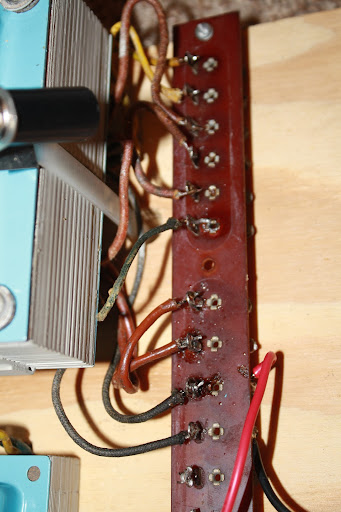
    Well here is the beginnings of my test board.

    I'm guessing that the yellow leads are the 5v taps, but I'm not sure what to use for the primaries. Can you tell just from looking?


    ~Semi-No0b Hobbyist~

    Comment


    • #17
      I would guess the yellow ones to be 5v for a rectifier tube. In American transformers, ther was a standard wire color arrangement, especially back then. Green would be 6v, yellow 5v, red was high voltage. Primary would be black. If present, high voltage center tap would be red w/yellow stripe. 6v center tap would be green w/yellow stripe. SOme had a bias tap off the high voltage winding, which would be blue. Others had a separate winding for it. Specialized tansformers, which the organ may well have needed could have other windings. I am not an organ man, but I have serviced tons of old jukeboxes, and as an example, they would have the common tube circuit voltages, but also a 24v winding to power relays and motors.

      Your wire colors still look reasonably visible in the photo, but colors age, and sometimes you can pull off the end bell, and the wires inside the thing will still show their original colors, as they were protected inside.
      Education is what you're left with after you have forgotten what you have learned.

      Comment


      • #18
        Ok, I'm guessing that the two blacks are the primary... does it matter which one sees the neutral?

        Also, there is just the one green wire. I'm thinking perhaps thats a 0v CT, and that one of the red pairs is my 6.3V and the other red pair is HV, but that still leaves a stray red wire unaccounted for... another CT?
        ~Semi-No0b Hobbyist~

        Comment


        • #19
          Originally posted by Enzo View Post

          Your wire colors still look reasonably visible in the photo, but colors age, and sometimes you can pull off the end bell, and the wires inside the thing will still show their original colors, as they were protected inside.
          When I had the ends off I looked, and the colors are not any more bright.

          I can probably figure it out once I get the primary hooked up. Does it matter which one I tie to the neutral?
          ~Semi-No0b Hobbyist~

          Comment


          • #20
            The 2nd lead from the left is the only green(it looks black in the photo). That's why I'm thinking that one of the red pairs is the 6v.
            ~Semi-No0b Hobbyist~

            Comment


            • #21
              OK, here are some voltages off the PT with zero load. The top two yellow leads will be 1 & 2, the top red pair will be 3 & 4, and so on...

              1 & 2 = 5.71vac
              3 & 4 = 799vac
              5 to mains ground = 15.9 [looks like a red with a faint stripe]
              6 to mains ground = 16.5 (green)
              [5 & 6 = 10.1vac]
              7 & 8 = 6.9vac
              9 & 10 = 121.1vac [primary]

              I also noticed that from mains ground to a transformer screw I read 4.1vac


              I did not use the limiter. A 2a 250v fuse did not blow.


              I was expecting to find 0v on the 5 and on 6.

              ~Semi-No0b Hobbyist~

              Comment


              • #22
                Voltage readings to ground from winding wires sticking out into space are meaningless. Unless you ground something, it has no reference to ground. Like trying to measure voltage on one end of a battery. Readings from the frame to the primary are just your meter picking it up. So this: set your meter to AC volts. Set the black probe on the table, not touching anything. Now squeeze the tip of your red probe between your thumb and index finger - make good contact with it. How many volts do you read? Right now in my shop I am only reading about a quarter of a volt, but some days you can get several volts. Your meter is picking up the radiated fields in your shop, the same way a guitar cord picks it up if you touch the tip of the plug.

                Power off, unplug from wall. Use your ohm meter to determine which wires have relationships. If you think one wire is a center tap, then it will show continuity to the other wires of its winding, and specifically, if a winding shows say 100 ohms, then the CT will measure 50 ohms to either end wire.

                Clearly the organ could not use 800vAC, which would rectify and filter to something like 1100vDC. It must have a center tap. SO if wire 5 might be that, first verify as I suggested, using ohm meter. But then with power applied, measure from 5 to 3 and 5 to 4, expecting to see 400vAC in each spot.

                COnsidering the transformer is not loaded, the voltages will be higher than normal, so 1/2 does look to be a 5v winding for rectifier tube, and the 7/8 do look to be 6v for tube heaters. And since all those seem to make sense, I agree, your black ones are the primary. That leaves 6. You do the ohm meter test and you will know if it is related to any of the windings or not. If not, see if it has continuity to the frame. It might be a shield inside.


                The primary is just a winding like any other, it is AC, so there is no polarity. It is a single primary winding, so there is no phase issue with a parallel winding. Neutral can go to either end.
                Education is what you're left with after you have forgotten what you have learned.

                Comment


                • #23
                  Sweet. So 5 is associated with HV.

                  3 & 4 = 147.5 ohms
                  5 & 3 = 76.7 ohms
                  5 & 4 = 70.5 ohms


                  And 6 is associated with 7 & 8(no continuity to frame), reading any combination gets me .4 ohms, but the value could be so low that I'm not getting a good reading....

                  And yep. 401v on both 3 & 4 in reference to 5
                  ~Semi-No0b Hobbyist~

                  Comment


                  • #24
                    As I predicted. That is why they pay me so much here...

                    I am sure if you measured resistance across 1 and 2 you would also get half an ohm or less. heater windings, whether 5v or 6v are high current and low voltage, which means relatively few winding turns of pretty heavy wire. That means its resistance will be VERY low. It will be difficult to measure with a meter. but if 7&8 are 6v, then see if you get 3v from 6 to either of them. If so, you have the center tap.

                    You now have the option of using solid state rectifiers or a tube. But do remember that when you power the 5v heater in a tube rectifier, it will be sitting at B+ voltage with respect to ground. Well with respect to that center tap anyway. I cannot assume it will be ground on a wooden plank unless you wire it there.
                    Education is what you're left with after you have forgotten what you have learned.

                    Comment


                    • #25
                      Originally posted by Enzo View Post
                      As I predicted. That is why they pay me so much here...

                      I am sure if you measured resistance across 1 and 2 you would also get half an ohm or less. heater windings, whether 5v or 6v are high current and low voltage, which means relatively few winding turns of pretty heavy wire. That means its resistance will be VERY low. It will be difficult to measure with a meter. but if 7&8 are 6v, then see if you get 3v from 6 to either of them. If so, you have the center tap.

                      You now have the option of using solid state rectifiers or a tube. But do remember that when you power the 5v heater in a tube rectifier, it will be sitting at B+ voltage with respect to ground. Well with respect to that center tap anyway. I cannot assume it will be ground on a wooden plank unless you wire it there.
                      Yep, 6 is the center of 7 & 8.

                      I now have the 6.3v bulb included as well as the 5v heater in a 5ar4.

                      I don't understand what you mentioned about the 5v heater sitting at B+ with respect to the CT(5). No ground circuit has been wired as of yet. I get 2.9vac in reference to 5 on each filament lead....
                      ~Semi-No0b Hobbyist~

                      Comment


                      • #26
                        DC....


                        Yep, getting 388.3vdc between heater and CT. Does voltage induce and invert from the plates to the heater? How does that work exactly
                        ~Semi-No0b Hobbyist~

                        Comment


                        • #27
                          Ever see a bird sitting on a high voltage power wire on a pole? The bird is gripping the wire at maybe 13,000 volts to ground, but he isn;t touching ground so he can be at any voltage at all, and never know it.

                          The heater IS the cathode of a rectifier tube. And that cathode will have your 388v or whatever on it. That means that with respect to the common, the heater wires then will also be at 388v to ground, because the heater and cathode are one and the same. But from pin to pin on the tube itself there is only the 5vAC. Like the bird, that 5v winding is blissfully unaware he is at such a high voltage.

                          Electrons flow from the cathode to the plates, and not the other way, that is how it rectifies.

                          I just didn't want you to lose sight of that in your breadboarding. The 6v heaters will not be so elevated.
                          Education is what you're left with after you have forgotten what you have learned.

                          Comment


                          • #28
                            Now I'm deciding how to filter the B+. I remember reading that a lower value on the filters would increase sag. How do I decide how many filter caps to use? I'm thinking maybe 16 uF would be a good place to start.

                            Also, I notice on some old Fender schematics, they use a selenium rectifier instead of a diode for the bias feed. Is there a difference in using the two, or are they pretty much doing the same job?
                            ~Semi-No0b Hobbyist~

                            Comment


                            • #29
                              The difference is that selenium is not available, is a weaker performer, is way less reliable, and stinks like nothing else when it burns. Sort of a burning rotten cabbage smell. ABsolutely no reason to try and use selenium instead of a 2 cent 1N4007 for your bias supply.

                              A couple suggestions. 50 years ago a value like 16uf would have been common. Nowdays 16uf is an odd value. Tolerances are not tight anyway, and certainly not critical, so the common 20uf or more likely 22uf would be a place to start.

                              I'd also suggest having a circuit in mind before building. You build a class A amp and there won't be any sag to increase. And just increasing sag by itself may or may not be desirable. What if it is already at a good level, you wanna increase it more anyway?
                              Education is what you're left with after you have forgotten what you have learned.

                              Comment


                              • #30
                                I just don't care for a 'tight' sounding amp, as a matter of taste. I don't have a frame of reference yet for when an amp will begin to sound stiff due to high filtering... that's one of the many things I hope to learn through this exercise.

                                As for a circuit in mind, I didn't really have one. I just thought I'd start with the bare power supply and build the sections, in order, toward the inputs. Once a power amp is complete, I can see how that sounds, and then tinker with the preamp section[s]. But I'm open to whatever is the best way to cover as much ground as I can, as far as learning goes.
                                ~Semi-No0b Hobbyist~

                                Comment

                                Working...
                                X