 Tweet
Tweet
Hello All,
I have a 1960's all tube Vox Cliff Richard Revervb unit Model "REV" by JMI-Jennings Musical Instruments and I was after a schematic diagram.
This reverb unit takes 2 guitar inputs as well.
These are pretty rare reverbs now.
I have looked at variuos sites and theres a lot of Vox schematics but not for this model even from the Vox site itself.
My reverb isn't working anymore because the crystal phongraph cartridges made by Acos model GP71 have had it.
You just can't fit a standard off the shelf reverb tank to it.
It would be nice if I could find out the specs for the ACOS GP71 crystal phongraph cartridges as well. I think I could get some other part to fit.
Anyhow, if anyone out there could supply me with a schematic or lead in the right direction to get one it's much appreciated.
Cheers
Alan52
 , holding the floating sub subchassis with 2 ceramic pickup transducers and the actual spring.
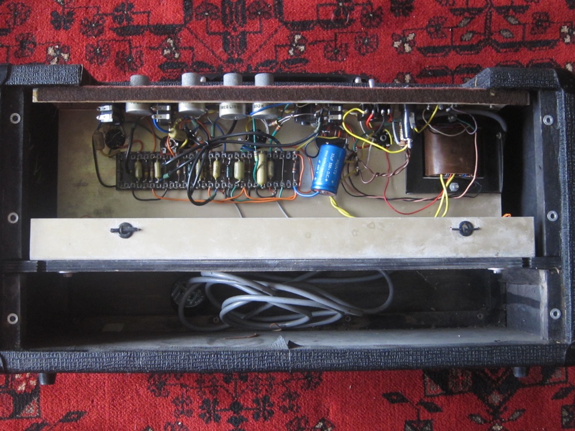

Comment