Announcement

Collapse
No announcement yet.

5F6A Bassman with 6V6's and other oddities

Collapse
X
 
  • Filter
  • Time
  • Show
Clear All
new posts

  • 5F6A Bassman with 6V6's and other oddities

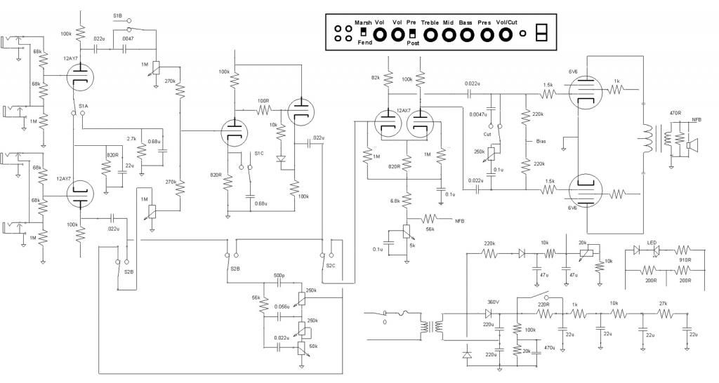
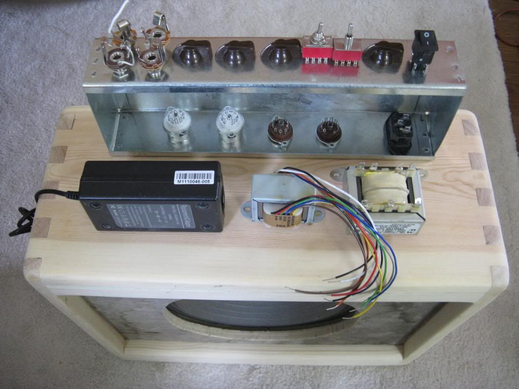
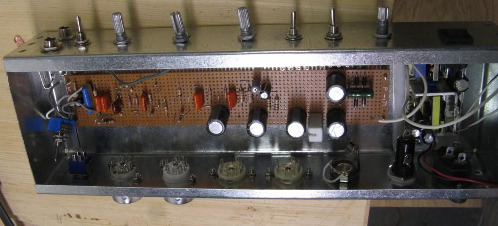
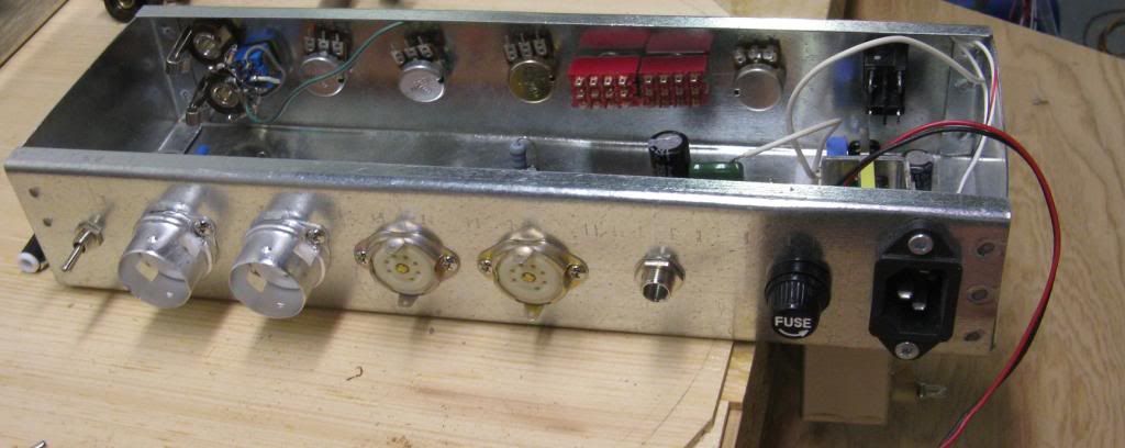
    Threw some ideas together and so far this is what still stuck together. The pre-post tone stack switch is an attempt to get a Blackface vibe going. Taking the TS off the cathode follower makes the other channel more gainiier, we'll see how that works out. The switch on the input cathode bias is to make the amp more Marshally along with dropping the bass with the lower value coupling cap and the 0.68uF cathode bypass on the cathode follower stage. The power amp section is pretty much a 6G3 Brown Deluxe. Not sure on the master volume/cut control yet. I was thinking of taking a signal off the cathode follower to go to a spring reverb and then returned to the other side of the PI with a off switch. Values can be tweaked, just stuck what looked right in. Thought I would run it all past you guys.


  • #2
    The only problem I see is that the bias supply won't work from the voltage doubler. It will need a series capacitor (and the diode is drawn backwards).

    I find that feeding both channels is very important in an amp like this. So much so that instead of four inputs, my next build will have just three. One for each channel and one that will feed both if there is nothing plugged in there.
    Click image for larger version

Name:	Inputs_3.GIF
Views:	1
Size:	2.6 KB
ID:	829160
    WARNING! Musical Instrument amplifiers contain lethal voltages and can retain them even when unplugged. Refer service to qualified personnel.
    REMEMBER: Everybody knows that smokin' ain't allowed in school !

    Comment


    • #3
      That looks like fun! You will get some very loud noises when you operate some of the switches due to different DC levels on each pole.
      I suggest you
      (1) Add 10 Meg across the 0.0047uF on S1B
      (2) Add 100K across the two poles of S1C
      (3) Add 10 meg to 0v on the 0.022uf that goes to S2B
      (4) Add 10 meg to 0v on the 0.022uf that goes to S2C
      (5) Use a couple of FETs to very, very, slowly switch bwtween the two cathode impedances on S1A
      Experience is something you get, just after you really needed it.

      Comment


      • #4
        Originally posted by loudthud View Post
        The only problem I see is that the bias supply won't work from the voltage doubler. It will need a series capacitor (and the diode is drawn backwards).

        I find that feeding both channels is very important in an amp like this. So much so that instead of four inputs, my next build will have just three. One for each channel and one that will feed both if there is nothing plugged in there.
        [ATTACH=CONFIG]23553[/ATTACH]
        Oops, pesky diode. Way back when I knew operation with a doubler needed a capacitor but forgot all about it, don't do this often enough. Actually changed my mind and am using a full wave supply now. At first I was not going to use the transformer because my 6V6's are 12V6's but then I decided to double the 6V supply and regulate the dc. Thanks for looking it over.

        Comment


        • #5
          Originally posted by nickb View Post
          That looks like fun! You will get some very loud noises when you operate some of the switches due to different DC levels on each pole.
          I suggest you
          (1) Add 10 Meg across the 0.0047uF on S1B
          (2) Add 100K across the two poles of S1C
          (3) Add 10 meg to 0v on the 0.022uf that goes to S2B
          (4) Add 10 meg to 0v on the 0.022uf that goes to S2C
          (5) Use a couple of FETs to very, very, slowly switch bwtween the two cathode impedances on S1A
          I did pretty much these things (except for the FET) in an amp that has similar switching. My real intent is not to switch the positions on the fly though, doesn't bother me to turn off the power for a couple of seconds to change them. I dig give it some thought and decided if I ever wanted to de-thump the amp I could just tack on some resistors.


          Oh yeah. thanks for looking it over guys.


          Ah, heck, you talked me into it, will put in the resistors.
          Last edited by printer2; 05-28-2013, 07:37 PM.

          Comment


          • #6
            Withoud depoping resistors.

            Comment


            • #7
              OK here are some other oddities. Posted this in another forum might be of interest. Now I have three amps to build (not including the one on the bench) The good thing is I already have cabs and speakers for them.


              I like Tweed tone controls but I also like the Blackface sound. Built an amp that switches between both and have drawn up a number of circuits with the Tone control and Treble and Bass controls but one day will try something like this. I posted a schematic on a previous thread switching between Tweed and Big Muff tone controls (scouped sound in the center high or low roll off if you turn it up or down) but it needed a dual pot for the Tone control. I got rid of the dual pot by going from a three pole toggle switch to a four pole. I will have to do a layout, could get ugly but a small pref strip might take care of the tone control section.


              Yesterday a guy at work sent me a link, seems he finally heard a Marshall 18 Watt and was all excited. I re-looked at a 18 Watt Lite and liked how simple the circuit was and thought I should just throw one together. But of course that would be too easy. Before I toyed with the idea of getting a 18 Watt and a 5E3 in the same chassis. So of course I had to start moving virtual parts around and think I have the essence of both amps in this design.

              Easiest if I explain it as the first switch (two switches sorry, I have some quality rotary switches that will do it on one control but I am thinking of others) changes the preamp section from a 5E3 configuration to a 18 Watt dual triode stage with a Tremolo channel tone control. When in 18 Watt position you can use either input and jumper the two together. That does leave the possibility of voicing the channels differently with cathode bypass caps and coupling caps but that would also apply to the 5E3. Thought I would leave it simple. :roll:

              So now that the front end is taken care of the two amplifiers have a different phase inverter, Cathodyne for the 5E3 and Long Tailed Pair for the 18 Watt. Another four pole switch here changes one to the other. I added an optional grid blocker on the Cathodyne just for good measure, the 470k resistors could be 1M if you want to stay closer to the 5E3, don't think it would matter much. You can switch between PI types with the preamp in either 5E3 or 18 Watt, would be interesting to hear a 5E3 with a LTP don't you think?

              I also added a master volume, another option some may not need. Output grid resistors, I went with 470k rather than the 220k Fender values due to the volume pot, should work either way. Now the output tubes, 6V6 or EL84? Pick your poison, I would use a 8k output transformer with either. Now if someone were really divided they could put in parallel dual sockets and pop in either EL84's or 6V6's with the proper cathode resistor on either. The screen resistor can remain the Fender 470R, the 100R resistor on a 18 Watt is barely helping.

              Now if someone were to put in dual sockets but were tired of popping the tubes in and out they could put in a three pole switch to select from either set of heaters and grounding the appropriate cathode resistor/capacitor. Saw Traynor do that and thought it pretty nifty. Or if you had a beafy enough heater winding you could just leave both sets of tubes on.

              Anyway, enough of the things you can do, how about the circuit? Will have to do a layout for this one also but that is for later. Need to calculate the power supply resistors also.

              Comment


              • #8
                I hate tight builds. Well that is what you get when you make a chassis out of off cuts from work. Looks like the 18W/5E3 will fit in a 10" cab. Might put the Bassman on hold for a little bit, not like I need the power. 1:1 transformer for HV,, switching supply for 12V heaters, 70V line transformer for output, might make a nice 8W amp with 12Bk5's or 12AQ5's.

                Comment


                • #9
                  Going with the 12AQ5's. Got some of the mechanical bits figured out.

                  The switch on the board is going to be the one on the bottom corner there, it is the cathode bias switch. Probably use it once and forget about it. Might go for full size pots, I have not looked through what I have on hand. Was a tight fit with the switching power supply as I am mounting it with the power transformer bolts. The power transformer is hanging off the chassis in the second picture. I probably will leave mounting the output transformer last as I am not sure if the 70V transformer will be adequate. I have a 15W transformer that I will compare it to and then decide. Used crappy 9-pin sockets, I had no others with a shield, even scrounged one from another project.


                  Comment

                  Working...
                  X