 Tweet
Tweet
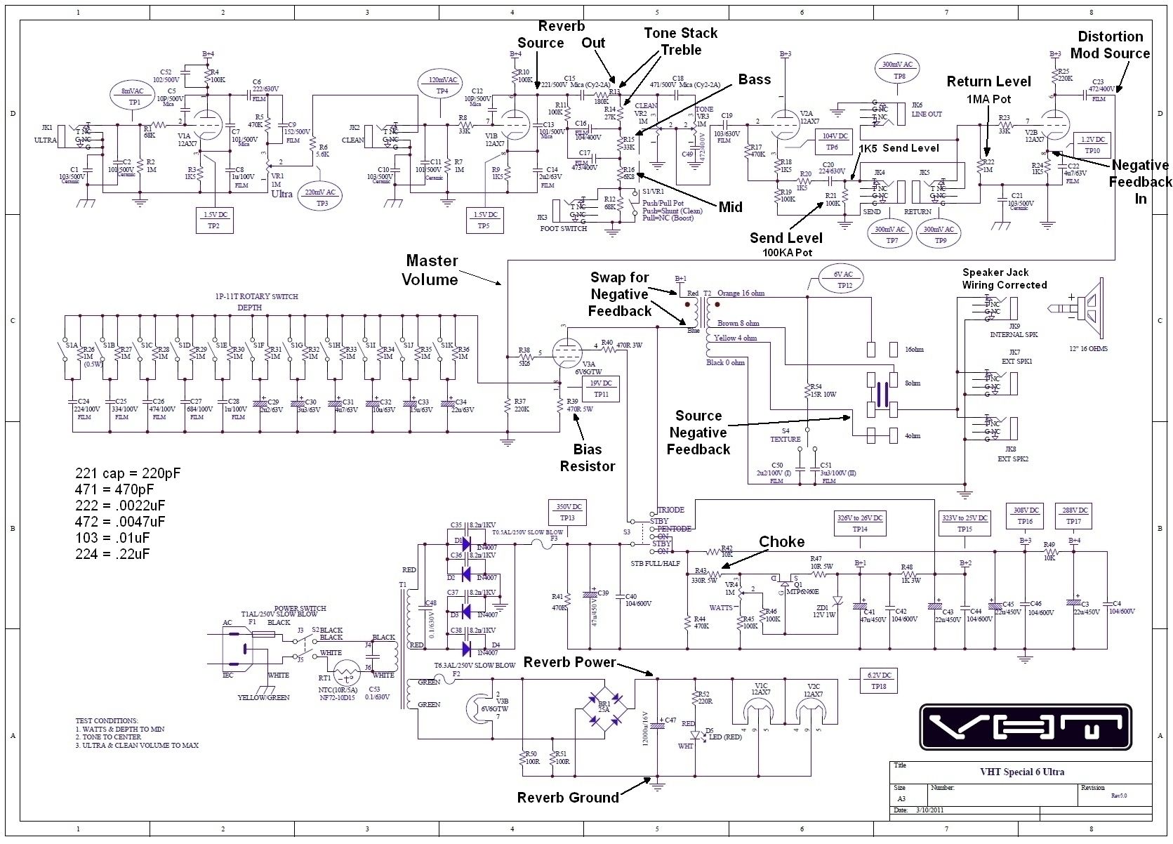
I just ran across the VHT Special 6 Ultra schematic and thought that there were some interesting features in it that we might want to borrow for our own builds and rebuilds.

Here is the schematic with mods suggested by robrobinette followed by a link to his mod page:
Amp Mods
I like how the one knob tone control is wired up. The signal goes through a BF tone stack (albeit with fixed resistors rather than pots) and the signal knob tone control is wired up to the volume control similar to the tweed deluxe. (It is drawn differently- I haven't redrawn it to see if it is identical.)
I like the 11 position "Depth" control which switches the 6V6 cathode resistor bypass cap going from .22uF to 22uF. Interesting range- I've always wired up a switch for values like 25uF, 50uF and 100uF with not a hell of a lot of difference between them.
The "Texture" switch selects the capacitor used in the conjunctive filter.
I like how they wire up the DC filament/relay supply from the 6.3vac supply going to the power tube. After the bridge rectifier and filter cap there is a 220R resistor in series with a red LED from positive to the negative ground. With this wiring you do not have to isolate the relay footswitch from chassis ground. It looks like the 220R resistor and red LED will keep the DC voltage around 6.2vdc with two 12AX7's and a single relay. I wonder how it would work with three preamp tubes and two relays... one way to find out and I DON'T mean theoretical computations. Hook the damn thing up and measure the voltages!
I've been using the AC-to-DC circuit that I borrowed from Mesa Boogie for almost 15 years and the downside was that I would have to select a series resistor to keep the voltage within an acceptable range depending on the number of tubes and relays hooked up. My D-clone had 3 relays and it was really tricky to get the voltage high enough to pull in all 3 relay coils yet low enough for the filaments...

Enjoy!
Steve Ahola
Here is the schematic with mods suggested by robrobinette followed by a link to his mod page:
Amp Mods
I like how the one knob tone control is wired up. The signal goes through a BF tone stack (albeit with fixed resistors rather than pots) and the signal knob tone control is wired up to the volume control similar to the tweed deluxe. (It is drawn differently- I haven't redrawn it to see if it is identical.)
I like the 11 position "Depth" control which switches the 6V6 cathode resistor bypass cap going from .22uF to 22uF. Interesting range- I've always wired up a switch for values like 25uF, 50uF and 100uF with not a hell of a lot of difference between them.
The "Texture" switch selects the capacitor used in the conjunctive filter.
I like how they wire up the DC filament/relay supply from the 6.3vac supply going to the power tube. After the bridge rectifier and filter cap there is a 220R resistor in series with a red LED from positive to the negative ground. With this wiring you do not have to isolate the relay footswitch from chassis ground. It looks like the 220R resistor and red LED will keep the DC voltage around 6.2vdc with two 12AX7's and a single relay. I wonder how it would work with three preamp tubes and two relays... one way to find out and I DON'T mean theoretical computations. Hook the damn thing up and measure the voltages!
I've been using the AC-to-DC circuit that I borrowed from Mesa Boogie for almost 15 years and the downside was that I would have to select a series resistor to keep the voltage within an acceptable range depending on the number of tubes and relays hooked up. My D-clone had 3 relays and it was really tricky to get the voltage high enough to pull in all 3 relay coils yet low enough for the filaments...
Enjoy!
Steve Ahola
Comment