Announcement

Collapse
No announcement yet.

I did something stupid to my JTM45 build

Collapse
X
 
  • Filter
  • Time
  • Show
Clear All
new posts

  • I did something stupid to my JTM45 build

    I had the working chassis sitting on a plank of wood, unpowered, and I knocked into it pretty hard, bending over the V1 tube enough to bend the pins a bit. I used the socket to straighten out the pins, pulled it out, and stuck it back in. Tried putting power to it and it blew the mains fuse. I pulled the tube out again and noticed that pin 3 had broken off and was stuck in the socket. I removed the broken pin from the socket and inspected the socket from both ends and everything looked good. Put a new tube in and now it's blowing the mains fuse when I engage the standby switch, no short with mains only.

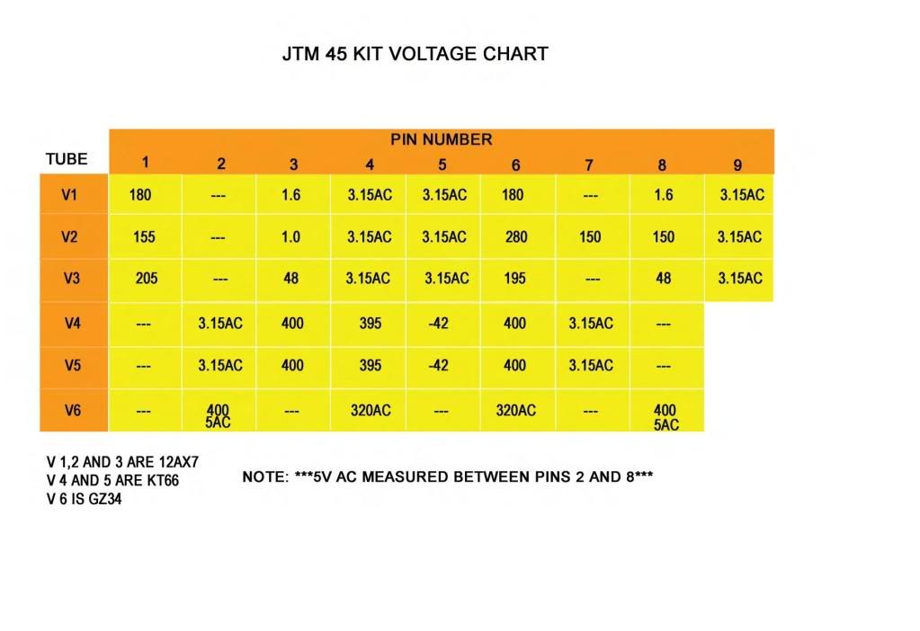
    I pulled out the old light bulb limiter and took some voltage readings on V1 with both switches engaged:

    P1 - 141
    P2 - 0
    P3 - .803
    P6 - 142.7
    P7 - 0
    P8 - .803


    I'm not even sure how to start troubleshooting this thing. What did I fk up?
    ~Semi-No0b Hobbyist~

  • #2
    This sounds like a forest for the trees situation. It sounds like you are looking so hard at the bent tube, you are missing a problem elsewhere.

    For a 12AX7 or similar, those voltages look perfectly reasonable.

    For the most part, the small tubes can't blow fuses. If I short the plate pins dead to ground (pins 1 and 6) the plate resistors usually limit possible current to maybe 3ma. Unless it was maybe a cathode follower.

    SO pull ALL your tubes. Hold each one up in front of your face, pins up, tap on the side of each with a fingernail. Does it sound like anything loose inside? Is there any loose bits collecting in the top of the tube? (Which is now at the bottom since they are pins up) Those are signs of possible damaged/failed tubes. Oh, and that black/mirror looking stuff coating the inside of the tubes? If that turns white, your tube is cracked and has air in it.

    With tubes out, now fire up the amp and see if it still blows fuses or brightens your bulb. Now install ONLY the rectifier tube. Does that fire up and make good B+? (sounds like it does) If the amp passes that test, install only the small tubes, and see if it still will hold a fuse or leave the light dim. And finally, if we get this far, install ONE power tube and see. Then remove it and install a different power tube.

    When you whacked the amp you bent a tube, and probably destroyed it, but you could well have damaged other ones.


    With all tubes removed, you can take voltage readings on all the sockets. Without tubes, the plate voltages will rise up to the B+ level, and the cathodes will drop to zero. But you can look at the power tube sockets to see that B+ is on the plate and screen pins and bias on the grid.

    Just because V1 has good readings doesn't mean all of them do.


    Plus the amp took a hit, so look for any loose hardware, screws, nuts, whatever, that could have been knocked loose and wedged under something and shorting it to ground.
    Education is what you're left with after you have forgotten what you have learned.

    Comment


    • #3
      Thanks for taking the time and thought to post Enzo. Always appreciated.


      With all tubes removed and with only the recto, the bulb stays dim. When I insert the 12ax7's, there's a momentary brightening of the bulb as the standby is flipped, but instantly goes to dim. With power tubes installed, the bulb stays brighter with mains only, and then when standby is switched it gets brighter after filaments have warmed up. Swapped out some known good power tubes and symptom is the same. Took readings with recto only, and with recto and output tubes. Readings are as follows.


      recto only

      v6-

      p2- 478dc
      p4- 340.2ac
      p6- 340.2ac
      p6- 478dc


      v5 -

      p3- 480
      p4- 480
      p5- -44
      p6- 479

      v6 -

      p3- 480
      p4- 480
      p5- -43.9
      p6- 480


      And with recto and power tubes installed


      v6-

      p2- 272.5dc
      p4- 246.2ac
      p6- 246ac
      p6- 272.1dc


      v5 -

      p3- 256
      p4- 256.8
      p5- -25.0
      p6- 257.1

      v6 -

      p3- 255.7
      p4- 257.2
      p5- -24.8
      p6- 257.1


      This all looks fairly normal to me.


      A few minutes later I decided to sacrifice a couple of fuses and discovered that it doesn't blow with the recto and power tubes installed. I put one more tube in, v3, and the fuse blew.

      Here's V3

      p1- 154.4
      p2- 10.6*
      p3- 17.46*
      p6- 152.5
      p7- 10.9*

      *V1 & V2 had .002 or so on the grid and .5 or so on p3

      So I have voltage on the grid and cathode. I should never have voltage on the cathode in reference to ground, and only mV on the grid, correct? I'm looking around to see where this voltage might be being picked up, but everything looks solid and separated.


      Sometimes I feel like I'm making headway learning electronics, but sometimes I feel like I haven't learned ANYTHING.
      ~Semi-No0b Hobbyist~

      Comment


      • #4
        Ok so after looking everything over, looks like my problem is ~11 vdc on the grids of v3.


        How it's getting there, I don't know. The amp got hit more on the tube of V1 than on the amp itself. I really feel like it would be unlikely to have damaged something else in the amp but I guess anything is possible...
        ~Semi-No0b Hobbyist~

        Comment


        • #5
          What about recto, and V1, V2 and V3 without the power tubes? Since V3 is the PI, the current that kills the fuse could still be coming through the power tubes, not necessarily through V3.

          So follow Enzo's flowchart and install the Rect and the small tubes (incl V3). I f everything's good then add the power tubes 1 at a time. Still with the limiter.

          edit: and yes, you are right about the biasing on V3. The grids on V3 should be the same as the other preamp tubes.
          If it still won't get loud enough, it's probably broken. - Steve Conner
          If the thing works, stop fixing it. - Enzo
          We need more chaos in music, in art... I'm here to make it. - Justin Thomas
          MANY things in human experience can be easily differentiated, yet *impossible* to express as a measurement. - Juan Fahey

          Comment


          • #6
            With only the power tubes missing, the bulb glows pretty dim. With a single power tube, in either socket, glows brighter. And slightly brighter than that if both power tubes are in. Not sure if that helps...
            ~Semi-No0b Hobbyist~

            Comment


            • #7
              Those V3 voltages look fine from here.
              It's a long tailed pair phase inverter.

              Comment


              • #8
                The problem is the loss of bias at the power tubes. You have -44 volts at the grids with the power tubes out. There is no way that voltage should drop to -25volts when the power tubes are installed.
                You said you tried other power tubes, so the problem is probably in the bias circuit itself.
                For starters you could check for AC voltage on the power tube grids when they are installed.
                Originally posted by Enzo
                I have a sign in my shop that says, "Never think up reasons not to check something."


                Comment


                • #9
                  According to this graph, v3 grids are out of whack...


                  ~Semi-No0b Hobbyist~

                  Comment


                  • #10
                    They don't list voltages for the grids of V3 (pins 2 & 7), so how can they be out of whack?
                    Originally posted by Enzo
                    I have a sign in my shop that says, "Never think up reasons not to check something."


                    Comment


                    • #11
                      Originally posted by g-one View Post
                      The problem is the loss of bias at the power tubes. You have -44 volts at the grids with the power tubes out. There is no way that voltage should drop to -25volts when the power tubes are installed.
                      You said you tried other power tubes, so the problem is probably in the bias circuit itself.
                      For starters you could check for AC voltage on the power tube grids when they are installed.
                      just checked. Negligible. Max .1 voltac
                      ~Semi-No0b Hobbyist~

                      Comment


                      • #12
                        Originally posted by g-one View Post
                        They don't list voltages for the grids of V3 (pins 2 & 7), so how can they be out of whack?
                        I'm assuming 0 is the target voltage.

                        --- ≠ 11vdc
                        ~Semi-No0b Hobbyist~

                        Comment


                        • #13
                          It will be easier if you post the schematic of this particular build.
                          Originally posted by Enzo
                          I have a sign in my shop that says, "Never think up reasons not to check something."


                          Comment


                          • #14
                            If memory serves, the only changes from this circuit were a couple of values in the bias circuit, and it sounded great for months before I hit it. Using KT66's
                            Attached Files
                            ~Semi-No0b Hobbyist~

                            Comment


                            • #15
                              Check the DC voltage on both sides of the 15K in the bias circuit (with power tubes in).
                              Originally posted by Enzo
                              I have a sign in my shop that says, "Never think up reasons not to check something."


                              Comment

                              Working...
                              X