 Tweet
Tweet
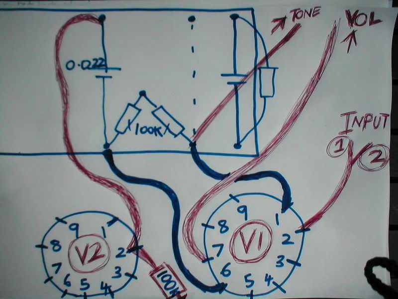
Hard to see from the photo but neither the .1uf nor the .022uf on the bass pot should be grounded to the pot body (looks like they could be).
-
-
Hi Mark, thought you must be on hols so didn't pester..Originally posted by MWJB View Post
Red wire does indeed go from vol mid lug to V1 pin 7 as to your previous post Q (neither bass caps grounded too).. and yellow wire does indeed go to free end of (680 pf) cap up at treb pot/ same junction the 100k (in pic tucked at fat bass caps feet) splits on to both bass caps.
I wonder if these are right though: this yellow wire mentioned, is starting on board at the junction of wire from V1 pin 1/ rhs 100k..
And from V2 pin 2 Ive a wire up to the top end of the (now only) .022 coupling cap, and a 470k to my gnd bolt on far right/ side of chassis..Comment
-
This should be clearer as to how Ive wired the pots/ yellow wire's starting place on board: if not, my diagram behind is exactly as its wired! (please ignore inferior caps as its a test.. if I can get this to work I'll replicate again with fancy caps)

Comment
-
The 5E3 can be too bassy but don't give up on it. It can sound great with a few mods. Wire it up like this -
http://cdharris.members.beeb.net/15W 6V6 Guitar Amp.pdf
The bass problem will be gone and you won't miss the lack of bass/treble pots.
Dave H.Comment
-
Thanks David, it'd take me another week to go through that to see what's different and how to simplify/ apply it to a stock 5e3- Im having enough trouble just trying to figure the way Im attempting at the mo it seems! appreciate the link tho- Captain.Comment
-
Yes wire from V1 pin 1 goes to treble cap & 100K slope resistor (bridges treble cap to bass & mid caps).
Wire to V2, pin 2 should come from coupling cap at V1, pin 6. That 470K is the grid load for V2, pin 2 and is correct (save for any personal tweaking of its value).Comment
-
From your latest pic the tonestack looks correct in principle. If all connections are good, this is not where your problem lies.Comment
-
Still no joy Mark- I rewired it back to 5e3 to check (it works) so rewired it back again with different tone caps (all continuity, connections, resoldered, using one channel only/ obviously checked which connected- thoughrally sure etc as always): as before- on flipping standby a 'BRR' & a loud huge bassy tone only (vol at 0, tones 4ish): turning any pot did nothing so quickly turned off..Originally posted by MWJB View Post
The only different bits Im using are 2x 470k lin tone pots (250k log should be) and the 680pf (250pf)- Im sure tho I should get something ok soundwise even with these to show me its feasable. The only other thing I see is on the PReverb layout's is V2 having links across pins, 5e3 not, but Im sure Mark would be aware of these/ the slightly different configs between the circuits.Comment
-
Isolate at which stage the "BRRR" is being introduced.
Use a jumper lead to ground out the signal at V1, 2, then at V1, 7, then at V2, 2. Wherever the jumper lead is when the "BRR" stops, it's the stage between that and the last place where you had the jumper connected, where your problem is. With the vol at "0" that SHOULD mean that signal at V1, 7 is grounded out at that point - so double check V1, 6 to V2, 2 (this should be the only change that you have made to V2).
Draw a layout directly from your amp's wiring, NOT from any cannibalised layouts lying around (so that you are drawing what you have ACTUALLY done). Even better draw a schematic (best to get in the habit of reading schems rather than layouts), signal goes in on the grid (2 & 7) & out on the plate (1 & 6) - break each triode down on by one.Comment
-
Yes I redrew a simplified diagram using your info & the plan from both circuits to be stupidly clear so I couldn't possibly get it wrong: I see clearly where on PR circuit Im pinching, what Im altering, & what Im doing to replicate it. Just to reitterate what Ive done, as it bafflingly only sounds like a wiring mistake to me:
Tones and vol pots wired as pic.
V2 (pin 2 only now differs):
--added a wire to the top side (to be exact- on the board right beneath 1cm away from the bright no.2 input jack) to the now only one remaining .022 cap. The bttm side/ other end of this cap is the unchanged junction to V1 pin 6/ one of a pair of 100ks.
-- & added an extra 100k directly from V2 pin 2 wired on to my preamp 'star' gnd bolt..
So pin 2 is now a junction for 2 things, previously just one to normal vol pot.
V1 (pin 7 only now differs):
-- removed one channel's input wiring to pin 7, replacing this with a wire to vol pin 2.
Replaced dropping Rs:
4.7k 2W with a white squarish (fwiw) 1K 3W.
22k 2W with original 4.7k 2W (just swizzled it round 180*).
All continuity checked inc between adjacent pins, dropping rs, pots, input channel, n/c input channel etc etc. Not possible Im using n/c input pair (sound is heard anyway). Using 2x 12ax7s. Nothing else removed, cut or altered ie link between pins.Comment
-
With the exception that you should still have a second .022 coupling cap between V2, 1 & V2, 7 (it is there in your photo), that all sounds correct.Comment
-
Im damn nr 100% sure whats done is correct, Im just going thru -again- in child's language as it were to be stupidly clear (I can see schems no probs but its WAY quicker to use layouts especially if Im so very stuck- and immediately clear to draw what Ive done for help):
Comment
-
That's spot on.
Have you identified at which stage you can turn off the "BRRR" by shorting the grid to ground yet? You have the overall concept, you just need to break it down to component parts to find & cure the problem.Comment
-
Hi Mark, I'll try this this ev now Im 100% sure it is correct; so rereading your previous post Im gonna..Originally posted by MWJB View Post
1. use a std wire jumper, ie with no resistor in series, between V1 pin 2 and chassis for gnd- flipping both switches on and hoping it dont go pop.. then
2. repeating with pin 7 (Im turning off & waiting between these) taking link off pin 2.
3. repeating same with pin 7 of V2.
Just being stupidly careful to check, as I noted there was ~120V iirc read at V1, 1 on its birthday voltage checks (friday 13th feb probably).
Apologies for another laboured bore of a thread to whoever is daft enough to be still reading this spiel.. Captain.Comment
-
Yes, that's the plan. You can't be too careful.Comment
Comment