That's not all that needs changing. Your screen supply should be from node C in your schematic. You screen voltages posted above are too low.
Power tube screen supply is definitely from node C with 470K resistors (with actual read of 510K). Should I reduce the value? I had noticed the screen supply dropped down into the 180's
Mort,
I may be misreading the photo/schematic but:
In the third photo you posted it appears the cathode bias bypass cap for the output section is located right next to the 200 0hm 10W bias resistor.The heat coming off that resistor will shorten the life of that cap considerably.
It would be preferable to use a cap with longer leads to allow considerable airspace between those two components. Your bias cap will love you for it.
SG
Power tube screen supply is definitely from node C with 470K resistors (with actual read of 510K). Should I reduce the value? I had noticed the screen supply dropped down into the 180's
Screen grid resistors should be 470 ohm. Not 470k. That WOULD explain the low screen volts. Sorry I missed that on the first post!!!
If you have a pair of 1K resistors you should use those instead. Better for modern tubes.
"Take two placebos, works twice as well." Enzo
"Now get off my lawn with your silicooties and boom-chucka speakers and computers masquerading as amplifiers" Justin Thomas
"If you're not interested in opinions and the experience of others, why even start a thread?
You can't just expect consent." Helmholtz
Screen grid resistors should be 470 ohm. Not 470k. That WOULD explain the low screen volts. Sorry I missed that on the first post!!!
If you have a pair of 1K resistors you should use those instead. Better for modern tubes.
Sweet. I'll see what I have. Is 1W ok for these resistors?
I corrected the B/C node goof up and the amp sounds a little more full without going into woofy territory. Not sure if that would be expected but it helped.
SG- I will address that too. I should be able to get it at least 1/4" away or more...
Oh wow, there it is. Now there's tons of punch, more volume, more clean headroom etc.
Still not woofy, which is good, and plenty of bass response. So great!
Here are the latest working voltages... I'm not cooking my tubes now am I ??
V4- 69mV across 1 ohm resistor
3- 444
4- 437 (441 before screen resistor)
5- .253
8- 36.79
V3- 65mV across 1 ohm
3- 442
4- 436 (439 before screen resistor)
5- .190
8- 36.64
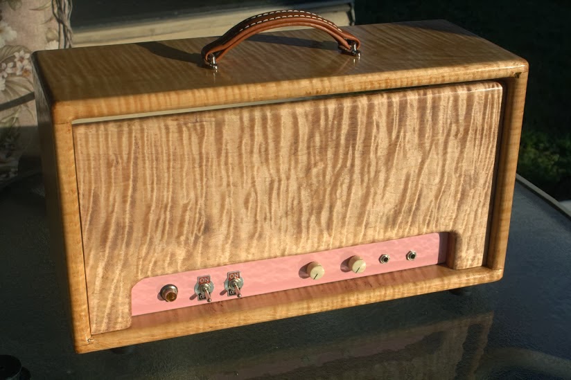
And here's a photo of what the build looks like. My friend doesn't come to this website so I hope it doesn't get back to him before he receives the amp
That's amp+ right there! Is that pink paint on the chassis or is it just the photo/lighting??? Enough curly maple to cap a Les Paul!
BTW, re the screen grid resistor rating... The current through that resistor will never reach a half a watt so the 1W rating is fine. Maybe better if we consider that a tube short often results in a blown screen grid resistor. In this case the screen grid resistor is a fuse protecting other components. You really don't want it to NOT blow. So just leave the 1W's in there.
"Take two placebos, works twice as well." Enzo
"Now get off my lawn with your silicooties and boom-chucka speakers and computers masquerading as amplifiers" Justin Thomas
"If you're not interested in opinions and the experience of others, why even start a thread?
You can't just expect consent." Helmholtz
I painted the chassis pink because I love Shell Pink on old Tele's and I kinda hope he's building me a pink Tele. Won't find out for another few weeks though.
Plus he's just gonna have to live with whatever I choose for him.. and it's all for fun so pink it is !!
As for the screen resistor... is there anything unhealthy about going back up in value some? When it had the high 470K in there it was very hairy and I liked some of that. Now it's very bold with alot of backbone and less hairy and I would like to get the right mix of hairy and bold.
Also, would someone remind me how to calculate the load on the tubes so I know that they are biased correctly not too hot not too cold?
Oh and btw I found that figured maple for about $1.90 a board foot. I was so giddy at the price that I bought enough to do 3 amp heads !! lol
Next time I go back to that town I might just buy an entire truck load. For their market they consider the figured maple to be trash wood and they sell it for a dirt cheap special price just to get rid of it !! I couldn't believe my ears when they told me that !!!
It's not super high grade AAAAA or anything but SO WHAT
I'm sure at some very high screen grid resistance there must be potential for problems, though I don't know what sort. 470k would be very high. I might be inclined to turn the amp over as the stock circuit since your friend reports that's his bag. I can't say how high you need to go before it's a bad idea but I'm sure you could experiment with values up to 22k. Past that I might be concerned about additional decoupling because of the higher resistance between the screen and the filter. 22k is nowhere near as high as 470k, but I wouldn't try that again.
It's possible the amp would sound sweeter at a lower Vp. With the screen circuit corrected what is your plate voltage? Did you match the PT specs for this design?
At the Vp listed above I would think that a 200 ohm shared cathode resistor may have the tubes running too hot. Measure the cathode voltage and divide by the cathode resistance. This is your current. Multiply that number by your "plate to cathode" voltage to get your "watts at idle" figure.
"Take two placebos, works twice as well." Enzo
"Now get off my lawn with your silicooties and boom-chucka speakers and computers masquerading as amplifiers" Justin Thomas
"If you're not interested in opinions and the experience of others, why even start a thread?
You can't just expect consent." Helmholtz
I'm sure at some very high screen grid resistance there must be potential for problems, though I don't know what sort. 470k would be very high. I might be inclined to turn the amp over as the stock circuit since your friend reports that's his bag. I can't say how high you need to go before it's a bad idea but I'm sure you could experiment with values up to 22k. Past that I might be concerned about additional decoupling because of the higher resistance between the screen and the filter. 22k is nowhere near as high as 470k, but I wouldn't try that again.
It's possible the amp would sound sweeter at a lower Vp. With the screen circuit corrected what is your plate voltage? Did you match the PT specs for this design?
At the Vp listed above I would think that a 200 ohm shared cathode resistor may have the tubes running too hot. Measure the cathode voltage and divide by the cathode resistance. This is your current. Multiply that number by your "plate to cathode" voltage to get your "watts at idle" figure.
Voltages after the screen resistor correction are listed in the post with the photos. I put 1 ohm resistors in series with the cathodes and get 65mV and 69mV across them, which should give me the current of 65mA and 69mA. Plugged into your equation should be 28.09W on V4 and 26.35W on V3 ??
Here are the voltages again.. For the Plate/cathode voltage I subtracted the cathode voltage from the plate voltage and then multiplied by the mV across each 1 ohm resistor.
V4- 69mV across 1 ohm resistor
3- 444
4- 437 (441 before screen resistor)
5- .253
8- 36.79
V3- 65mV across 1 ohm
3- 442
4- 436 (439 before screen resistor)
5- .190
8- 36.64
Looks like I might be a little hot. Upping the screen resistor value will drop the idle wattage, correct? (since I'm interested in upping anyway)
And as for the PT(and OT), I just used what I had on hand which was a 1966 Fender Bandmaster transformer set (original). I figured that going from a 2x6L6 amp to another 2x6L6 design would be problem free.
 Tweet
Tweet

Comment