 Tweet
Tweet
I'm working on a SLO clone with dual EQ stack on a ampclones SLO100 PCB. I followed the BOM list and official SLOcone schematics. I've built many regular SLO clones before so this baffles me!!
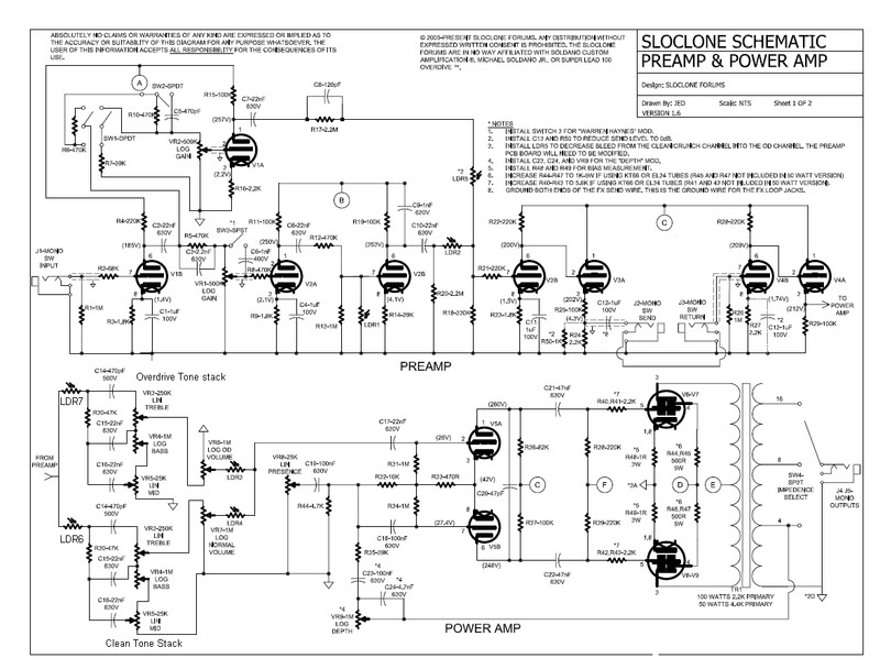
Overdrive channel works OK, all controls work. When I switch to Clean I only get a pop and faint sound at Max gain (probably a bleed from the OD channel) The Volume and EQ controls have no effect.
Troubleshooting
1. I ran line from FX loop send to another amp and had same result. loud/normal overdrive signal and faint clean/bleed signal
2. replaced V1 tube -no effect
3. replaced C7-22nf Coupling cap - no effect
4. replaced LDR5 and LDR4 VTL5C1 - no effect.
5. Bypassed clean/crunch switch circuit going from board to gain pot -no effect
6. Bypassed LDR5 with jump from R17 to R21, I got a boost in volume but still not much. still very low compared to OD
7. Checked voltage at V1a Pin 1 & 3 to be normal range
8. cant be heater issue since OD sound awesome
9. Since running 7 LDR's changed switching circuit power suppply resistors R64 from 47ohm to 15ohm & R65 33ohm to 15ohm.
I've traced the board out and this channel is to small to give me such a big headache.
Any Ideas how to resolve this.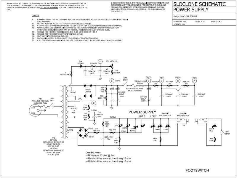

 Thanks!!

Comment