Hopefully it did not damage your new speaker. Disconnect it and do not reconnect until the amp is repaired, and verified that there is no DC on the output.
Here are the pictures. I'll attach later the burned out transistors that I can see (better pics I mean). I really appreciate all ya'll's help with this issue. Looks to me that the MOSFETs are toast. Brown corrosion with bubbles never seems good. I'll get to testing them soon. Thank you guys again!
That's the good news.
A quick glance at the pics and I see 2 output devices have been replaced with ECG. They should have all been replaced with the same brand. And they are bi-polar transistors, mosfet's are in the other version with the SMPS.
Also R622? under the goop over by jack J615 looks fried.
Gheesh that major picture and you pick out the tiniest resistor I would have looked over 1200 times....awesome man, thank you.
glad to hear about the linear supply. I'll assume that's the 1" square box on the smaller board...
I've not messed any with those ECG transistors, however I will replace them all with the same brand. I'll keep the bi polar transistors in mind when I'm replacing them. I'm guessing it will be easier to buy 4 all the same brand and keep it simple. As far as the resistors I replaced, (r683, r602, r612,r655b the grey ones) I'm hoping they match the original equipment seen in r605, r604 (green). I can't tell as they're all heating up since I have yet to find the short that's kicking my butt currently
Also noted the fried transistor near r655b (black headed one... mps a56 eb302).
Where do you guys buy the supplies to repair/build these? Google isn't proving too helpful. Thanks for all the help!
Actually I need to see an optometrist, that was just lucky. I did score .6hz on that tone perception test someone posted the other day, but I think I might have done better using more replays.
The proper transistors will be Tip35 and Tip36. The ECG brand are aftermarket general replacement types that are generally frowned on and much more expensive.
Best places for these type of parts are electronic component suppliers like Mouser, Digi-key, Newark, etc.
You will want to build a limiter lamp/dim bulb tester to avoid blowing up your new parts.
Originally posted by Enzo
I have a sign in my shop that says, "Never think up reasons not to check something."
i have the schematics that OC D gave me but man it takes forever to find the corresponding part on the board and the sheet of paper. Anyway, I'll replace the resistors that are blown, buy 4 of the same TIP 36 transistors. Forgive my ignorance but do I want high power TIP36 or 100v or what? There are too many options for my ignorance. Thanks!
Via Digikey anyway, the higher voltage rated part is cheaper, so why not go that way? These are maximum ratings and the rail voltage in this amp is +-45V so either the 60V or 100V would work. Just use all the same parts. AND BY THE WAY, two of those are TIP35's! Don't put 4 TIP36 in the amp. It is a push pull amp with two PNP and two NPN transistors.
Yep, two TIP35C and two 36C, the C denotes 100V version.
But wait, are you getting these shipped or do you have a big parts house handy? You want to order every thing you need in one shipment.
You mentioned an MPSA06, there may be more. And you should replace the drivers also, a TIP29C and two TIP30C.
If you are ordering a shipment, you should locate all your bad parts before ordering.
Originally posted by Enzo
I have a sign in my shop that says, "Never think up reasons not to check something."
If your power rails are +/-45v then you need 100v parts. When the one side conducts heavily and the opposite stops, then the output runs close to that rail. WHich means the off transistor has pretty much both rails across itself.
The whole smaller board is the linear power supply. Well the board plus the transformer hidden inside the amp. The board that says 206-0084-A26. The square thing next to the fuses is a bridge rectifier.
Education is what you're left with after you have forgotten what you have learned.
If your power rails are +/-45v then you need 100v parts. When the one side conducts heavily and the opposite stops, then the output runs close to that rail. WHich means the off transistor has pretty much both rails across itself.
The whole smaller board is the linear power supply. Well the board plus the transformer hidden inside the amp. The board that says 206-0084-A26. The square thing next to the fuses is a bridge rectifier.
I have a good-sounding parts place here in town. I'll head over and see if they're as good as they claim. If nothing else they can help me find all the parts to order and replace. Thank you for the help.
Thanks to all your helpful comments, I now have a rockin bass amp back! Thanks much! Ended up replacing most of the in-series transistors, a few resistors, and a fuse or two. Thanks again for all the help!
Hi everyone. Glad to see someone solved his problem.
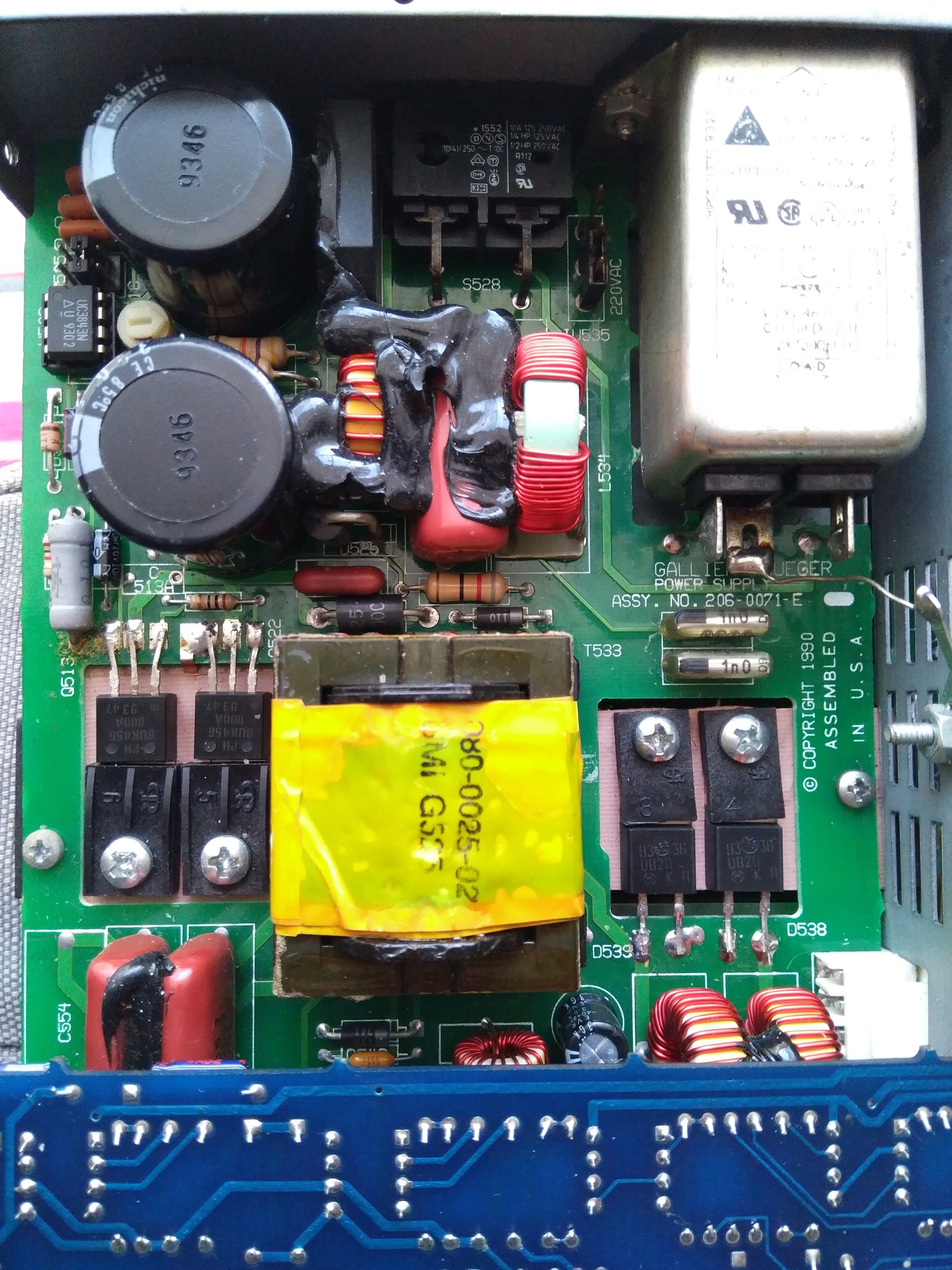
I have the same amp from the same era, with the same problem, with a bit different power supply unit. This is how my power supply board looks like.
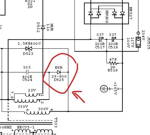
I bought it second hand several years ago, played quite well since then. However one day it stopped working. Checked the fuse which was blown, replaced with the new one, played well for a couple minutes and blown again. Apparently the output transistors were fine, so I checked the power board visually, everything seemed to be ok. Since the high current AC always scares me, I sent the amp to a repair shop. The guy said he changed some diodes and it is in working condition. Brought back to home, played a couple more minutes and the fuse has blown again. Then I came across this thread. Downloaded the schematics and found that the diode D525 is shorted.
Replaced it with the same one, verified the voltages, mounted in the amp, powered up, played for a couple of minutes and BAM, both the fuse blown but diode were intact this time. Every time I replaced the diode, it got worse. This time the board itself has shorted, from the tip of the diode to the pathway of bridge rectifier. See the image below.
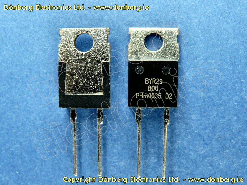
Resoldered the tips, removed excess solder, cleaned the soldered area with alcohol, covered the exposed part of the pathway and the gap in between with nail polisher, put all the things together, powered up, played for a couple of minutes, sounded good without any electrical noise and both the diode and the fuse are blown after minutes. With frustration I quit trying. Then I have noticed that the D525 in the schematics is BYR29-800, but my board has 1N5408 instead. I don't know if this is an issue because it was working fine for 2 years with this diode (I have a picture of it before I have sent it to repair shop, so obviously servicing guy didn't changed that diode.)
Sorry for the long post, I am out of options. Sent a mail to GK today, but did not get an answer yet.
I am living in a small area and the repair shops are not competent enough to solve this.
One of them even refused to check it, don't know why. So I'm on my own on this. What else should I check? What might cause this diode to keep blowing?
First and for best results, you should start a new thread for your problem. This is a 5 year old thread and probably most are not paying attention to it any more. That aside, are you buying parts from a reputable source? There are many poorly constructed fakes out there these days. I also see what looks like a cold/cracked solder joint there that needs attention (circled red), whether that is the cause of the problem or not.
"I took a photo of my ohm meter... It didn't help." Enzo 8/20/22
 Tweet
Tweet


Comment