Announcement

Collapse
No announcement yet.

Voltage Divider Math in a Bias Supply.........

Collapse
X
 
  • Filter
  • Time
  • Show
Clear All
new posts

  • Voltage Divider Math in a Bias Supply.........

    I'm going to be doing a bit of troubleshooting on my Oliver PA-100X, today (Sat). Before I get into lifting components to take measurements, I would love to know the math that goes into getting the results needed.

    My actual voltages are:

    418vAC - to the 100K resistor (R1)
    -37vDC - after the diode (at it's junction with R3)

    Simple voltage dividers, I understand: Vout = Vin x R2 / (R1 + R2). But, I'm missing something on how the 47K (R3?) comes into play after the diode, to get the -50vDC.

    My Ampeg B-12-XY has the same bias supply, except R3 is a 34K. I made a voltage chart for that one, and will do the same with this one, when I've ironed out the issues. The XY has 417vAC in and -52vDC out.

    If someone would please do me a favor and demostrate the math for this circuit, I would greatly appreciate it. Math doesn't come easy these days. Thanks for all help. Have a good one.

    Jack
    Attached Files

  • #2
    Originally posted by Jack Hester View Post
    If someone would please do me a favor and demostrate the math for this circuit, I would greatly appreciate it.Jack
    I’d normally just simulate it but I’ll have a go.

    R1 and R2 form a voltage divider with an output resistance of R1//R2 so with 418V input the divider output voltage is 150V with an output resistance of 35.9k. The 150V is then divided down by a second voltage divider formed by 35.9k and the 47k (R3) so the voltage is 150 * 47/(39.5+47) = 85V but the cap only sees half of this because of the diode ie. 42.5V. Assuming the 418V is RMS we need to multiply 42.5 by 1.11 because the cap will charge up to the average value not the RMS so we now have 47V.

    1.11 is the form factor of a sine wave which is RMS/Average value. For a sine wave RMS = peak/sqr(2) and average = 2/pi if I remember correctly so that’s 0.707/0.637 = 1.11

    Comment


    • #3
      Originally posted by Dave H View Post
      I’d normally just simulate it but I’ll have a go.

      R1 and R2 form a voltage divider with an output resistance of R1//R2 so with 418V input the divider output voltage is 150V with an output resistance of 35.9k. The 150V is then divided down by a second voltage divider formed by 35.9k and the 47k (R3) so the voltage is 150 * 47/(39.5+47) = 85V but the cap only sees half of this because of the diode ie. 42.5V. Assuming the 418V is RMS we need to multiply 42.5 by 1.11 because the cap will charge up to the average value not the RMS so we now have 47V.

      1.11 is the form factor of a sine wave which is RMS/Average value. For a sine wave RMS = peak/sqr(2) and average = 2/pi if I remember correctly so that’s 0.707/0.637 = 1.11
      Thank you ever, ever so much! Now, I'll go digest this and maybe get in a little testing this afternoon. Have a good one.

      Jack

      Comment


      • #4
        Spent some time playing with the math. Then, I rolled it into a very small program, to play with it some more. Requires no installation. Just extract and run.

        Jack
        Attached Files

        Comment


        • #5
          Dave -

          May I ask that you check my thoughts on the math for this '59 Bassman bias supply?

          Looking at the attached drawing, the AC volts enters on the bottom left, from a tap (???vAC) on the PT secondary.

          I would normally multiply the say 60vAC by .707, to get half the peak. And applying what you stated for the last supply, would I then multiply it by 1.11, to get an average DC (V2) of -47.1vDC, because of the first capacitor?

          Next, applying my voltage divider rules, I will say Vout = V2 x (R2 / (R1 + R2), where R1 is the 15K, and R2 is the 56K. This gives me -37vDC.

          Of course, that doesn't match what the schematic shows for a Vout. But then, I don't know the AC feed voltage to this circuit.

          Mainly, I want you to check my math, and my thinking on this circuit. Thanks.

          Jack
          Attached Files

          Comment


          • #6
            Seems to be from a 5F6A?

            Without knowing the AC voltage we are starting with, it is hard to make calculations.


            Not sure I followed the math.

            In your Bassman with 48v on the bias node, I;d then expect to see about 60v at the diode. (60v into a 15/56 voltage divider yields close to 48v)

            When I see a rectified AC with a filter cap on it, I expect the cap to be charging to the peak voltage of the AC. SO I calculate roughly 42vAC at the start. (.707 of peak) So in my head, I get:
            42vAC, rectified and filtered to make 60vDC, then through the 15/56 divider to make 48vDC for bias.
            Education is what you're left with after you have forgotten what you have learned.

            Comment


            • #7
              Enzo -

              Thanks for your feedback.

              I don't have one of these amps, but I am curious as to how they get the bias voltage to be what it is. The only reference that I have to what the bias tap on the PT would be is that of a replacement transformer. Those have a 50vAC tap (loaded value). I agree with your math, that there should be a -60vDC from the diode, and just before the voltage divider. I can't make 50vAC turn into -60vDC. Or the opposite. -60vDC into 50vAC. That's where I'm stumped.

              Jack

              Comment


              • #8
                Well, you are just going to have to measure the AC voltage we get to start with or know someone who has. rectify and filter 50vAC and you get 70vDC. I am ignoring the voltage drop across the rectifier diode and other tiny details. I don't assume I have 50v just because a catalog says so.

                And what does loaded mean? If that winding is rated say 1A, then loaded is when 1A is being drawn. Your bias circuit draws almost nothing, so a loaded spec will not apply.

                The resistors in the divider make a 4/5 ratio more or less, so whatever DC we make at first, 0.8 of it will become bias.
                Education is what you're left with after you have forgotten what you have learned.

                Comment


                • #9
                  This calls for a breadboard project. Sometime tomorrow, I'll go out to the shop and build this circuit on the breadboard. Then, with unknown input AC, I'll slowly increase the supply until I have -48 on the output. I'll know for sure what the initial rectified voltage will be at the diode, and the supply needed to get the output.

                  Even though I'm not a whiz at math, I still try to make it work, and prove what I'm actually seeing. I've completed the troubleshooting on my original circuit, that I began this thread. The issue was a bad cap strapped across the 47K resistor. When that was replaced, my PT secondary also increased a bit. It rose from around 418vAC to 429vAC. My bias voltage jumped from -37vDC to -57vDC. I needed it at -51, to get my bias current in line with the 536vDC plate voltage that I now had.

                  I removed the 47K resistor, and soldered a 24K resistor in series with a 25K pot, its wiper tied to the same outside lug as the resistor. The other outside lug was tied to ground, while the resistor was tied to the output side of the diode. I am now able to roll this bias to the rated (70%) current.

                  Point is, the calculated AC before the diode is around 150vAC. The actual measured voltage is 107vAC. I have not worked that one out, but the calculated output is just shy of -49vDC. I'm pleased with it being this close.

                  Anyway, we'll see how the Bassman circuit checks out on the breadboard. I even have the 8uf caps. More to come. Have a good one.

                  Jack

                  Comment


                  • #10
                    8uf, 20uf 100uf, that will not affect it

                    My discussion was about the Bassman circuit, not a circuit dropping from high voltage like you started with.
                    Education is what you're left with after you have forgotten what you have learned.

                    Comment


                    • #11
                      Originally posted by Enzo View Post
                      8uf, 20uf 100uf, that will not affect it

                      My discussion was about the Bassman circuit, not a circuit dropping from high voltage like you started with.
                      The Bassman will be the one to go on the breadboard, as I already have the other in a functional amp. And, I should have the exact component values, from a Bassman project that never materialized several years ago. I'll post the results.

                      Jack

                      Comment


                      • #12
                        Originally posted by Jack Hester View Post
                        The Bassman will be the one to go on the breadboard, as I already have the other in a functional amp. And, I should have the exact component values, from a Bassman project that never materialized several years ago. I'll post the results.
                        Ok. Real conditions on the breadboard.

                        First, the components used for the test on the Bassman Bias Supply;

                        2 - 8uf-150v capacitors
                        1 - 15K resistor - Carbon Comp - Measured @ 16.71K
                        1 - 56K resistor - Carbon Comp - Measured @ 60.11K
                        1 - 1N4007 diode

                        Circuit was wired according to the Fender '59 Bassman schematic, and AC voltage was applied (by auto-transformer) until 50.03v was reached.

                        DC voltage was measured at the junction of the diode and the first 8uf capacitor, and found to be -65.4v.

                        DC voltage was measured at the junction of the 15K (16.71K), 56K (60.11K), and the second 8uf capacitor, and found to be -51.13v.

                        I calculated in reverse, through the 15K/56K voltage divider and got -65.34vDC. That is, using the actual resistor values.

                        I am more than satisfied with these results. Confirms that the AC supply to this circuit is 50vAC. Now, to figure out the math behind the 1.306 multiplier that steps the voltage up to that entering the voltage divider.

                        Jack
                        Last edited by Jack Hester; 09-20-2014, 02:58 PM.

                        Comment


                        • #13
                          Good luck.

                          You are missing a few volts. Is this on a breadboard for real or wired up in an amp chassis. That is to ask is that 65v reading taken right across the 8uf cap? Or inferred by a chassis to cap + end reading? Your diode will drop somewhere in the 0.5v-1v range, for instance.
                          Education is what you're left with after you have forgotten what you have learned.

                          Comment


                          • #14
                            Originally posted by Enzo View Post
                            Good luck.

                            You are missing a few volts. Is this on a breadboard for real or wired up in an amp chassis. That is to ask is that 65v reading taken right across the 8uf cap? Or inferred by a chassis to cap + end reading? Your diode will drop somewhere in the 0.5v-1v range, for instance.
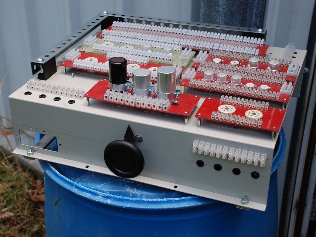
                            The whole test was on this breadboard:


                            and reading was taken across the second capacitor. The circuit was constructed on the long layout board, and the built-in auto-transformer used to obtain the correct input AC voltage.

                            Jack

                            Comment


                            • #15
                              far out, that's a cool unit.

                              You might explore voltage drops across the many connections. All the interconects might result in a volt or two loss through the circuit. That will throw off any precise rations if that is what you are seeking.
                              Education is what you're left with after you have forgotten what you have learned.

                              Comment

                              Working...
                              X