Announcement

Collapse
No announcement yet.

Help Wirring Bass Guitar on board preamp

Collapse
X
 
  • Filter
  • Time
  • Show
Clear All
new posts

  • #16
    The list of mistakes I found so far on the schematic:
    - IC1C is actually IC1D and IC1D is IC1C,
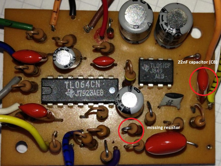
    - C8 capacitor is rather 22n and not 22uF,
    - there is one missing resistor on the schematic. It is marked with red circle on the photo below. It goes from C5 (after the input buffer) to pin #6 of IC1B. I'd like to know its value. What is funny is that dwmorrin has it on his quick sketch :-).

    Click image for larger version

Name:	preamp_top.jpg
Views:	1
Size:	188.4 KB
ID:	836728

    Mark

    Comment


    • #17
      Assuming that you can buy Switchcraft jack with double isolated switches for the batteries, the preamp could look like this:

      Click image for larger version

Name:	Oakland_SVF.png
Views:	1
Size:	38.2 KB
ID:	836731

      I'm not sure about the switch, 22n capacitor, 27k resistor and 10k resistor from the switch to pin #9 of 1C opamp. The rest looks reasonable. I assumed that the missing (17-th) resistor is 4.7k. I hope that the OP can verify this.

      Mark

      Comment


      • #18
        Hello,
        First of all I would like to thank you so much for all your help and effort,
        Hope one day I can re-tribute in the same way. Thanks

        I read everything in this thread, all the comments and tips.

        I will start by answering the all the questions that were raised:

        "PAD?? is the input for IC2, and I would suspect this is the passive signal input due to the high impedance.
        ORANGE_STRIPED looks like the main output."


        Thank you, that really made a huge difference in the way I looked to the circuit.
        I redraw the schematic today with that input and output in mind.

        "The problem is that I don't see the "virtual ground" circuit. Is it possible that to made a mistake while drawing the schematic?"

        Therese actually no Virtual ground in the circuit PCB, but I can easily do one outside the board and power the circuit that way, it seems to me the best solution.

        "I just thought that if D1 and D2 were Zener diodes, they would form kind of virtual ground circuit. But much better results could be obtained with just 2 resistors so maybe I'm wrong."

        I de-soldered the Diodes and checked to see if they were Zeners or not. They are not Zenners, they are normal diodes, protective diodes in this case.

        "I'm surprised with the large values of the capacitors (C1, C2, C3). Are they correct? Maybe they used "state variable filter" circuit: State variable filter - Wikipedia, the free encyclopedia ?"

        Cap Values are correct, I re-checked all the values and took a picture

        Click image for larger version

Name:	CapValues.jpg
Views:	1
Size:	184.1 KB
ID:	836732

        "State Variable Filter", Yes I think you are totally correct, it starts to make more sense now. Thanks a lot for bringing that up.


        "so the camera is fixed (that or they have incredibly firm hands) and take pictures of both sides of the PCB (what you did) but making certain that the board itself is exactly perpendicular to the camera, and at exact same distance , so one picture can be flipped , set to 50% transparency (so you can see through it) and superimposed exactly over the other.
        Imagine you look at your PCB from the component side but the PCB itself is made out of transparent acrylic or at least semi transparent tracing paper. so you can see parts and tracks at the same time."


        I Did as you sugested, took high Res pictures, Im now trying to learn how to do that in photoshop, when I finish it I will publish here.
        Thanks its a great suggestion

        "Is it this bass: Oakland bass | TalkBass.com ?"

        No its not that bass.
        That one is even more weird with an XLR output in the front and 4 Mini Toggle switches, Weird stuff.

        "on Talkbass one of the guys has similar bass. What if you ask him to make a photo of the preamp in his bass?"

        Thanks, will search for it and ask for pictures.
        Anyway I already searched a lot for Oakland Basses on the web and cant find much info.
        I actually dont know the model of this bass and the Oaklands I found have the same configuration as the one in talkbass.
        This one has much less holes in the Body

        Click image for larger version

Name:	BodyPotandSwitchholes-notes.jpg
Views:	1
Size:	95.6 KB
ID:	836733

        "Seems a bit more complicated than just wiring the battery snaps as they should be, no?
        Using +/-9 means the OP can get straight to work on this thing.
        Converting to +18 means putting 2 extra resistors and a cap on an already crowded board. Are you sure that's the advice you want to give?
        This guy just wants to get it working. Let's try to keep it to that... and then we'll redesign it.
        And yes, the 18V switched via the input jack is what any of us would design if we were building this from scratch... "


        Yes, exactly, for now I will stick with the battery snaps, and get the ground from the middle of the batteries, its enough for testing and to get it work.
        When its working I can then add a small board with the virtual ground

        "The OP could help clear up some of this by explaining if the active circuit was always in the same bass or if this is some sort of transplant job or what... more details the better. "

        I'm really sorry, but I have no details whatsoever.
        The Bass was bought used/as is, electrically everything was disconnected or messed up, someone probably wanted to change the electronic circuit disconnected the original connections. Then had no time to go through with it and sold the Bass, that's at least what I think might happened.


        "I still think that this preamp is a little bit different from typical bass preamp. In the 70-ties Alembic used preamps based on "state variable filter" principle. In general it was kind of active "Varitone" circuit. Several companies copied their preamp. Maybe this is one of such preamps"


        Like J M Fahey said "Jackpot" this is really a great breakthrough, and that schematic will help a lot to understand whats going on with this circuit and hot to connect it.

        "I think so because on the schematic there are 16 resistors but on the PC board photo I see 17 resistors."

        "which might be explained by the mystery resistor and rechecking the circuit, we might have missed something else."

        "one resistor on the schematic is missing. There are 16 resistors on the schematic and 17 resistors on the board. 17-16 = 1 is missing."

        C8 capacitor is rather 22n and not 22uF


        I re-checked the schematic again, it was more easy this time to trace the circuit since Im more familiar with it now. The first time I traced it I was completely lost.
        You were completely right there are there are 17 resistors on the PC board soone resistor was missing, but its not part of a virtual ground.
        Its a 2K Resistor and connects IC1B Pin6 to R12 and C5.
        The circuit makes much more sense now.
        Also Mark and dwmorrin were right when I did the first schematic I made a mistake and swapped IC1D and IC1C.
        And Mark was spot on also the C8 capacitor is 22nf and not 22uF.
        The new schematic has this fixed also.
        Also I think the layout is much better now, makes more sense and its easier to understand. Will publish the shematic in the next post.

        "There must be some reason why an earlier owner said WTF and just wired it passive"

        The earlier owner could have been on an LSD trip and decided to destroy things also! LOLOL

        The Active part was not taken to wire it passive. Active and Passive part were not wired or not completely wire.
        Bass was not making any sound.

        The passive part was connected by a luthier when he received tha bass to fix it, no parts were added (pots, switches) or taken from the circuit.
        He just did a simple passive connection to put it to work and then asked for my help for the active part.
        And here we are, and Im quite confident that step by step the circuit will make more sense and we discover more connections.

        "The OP could simply tell us what Jack is currently installed in the bass and this would solve the problem."

        Its a normal/common Tip, Ring , Sleeve jack no tricks there.

        "Their inputs are connected to dual 2x50K pot (and not 2x56K)"

        The Dual Gand Pot doesn't have anything written, I measure 56K on it with a multimeter, with the high tolerance on Pots (10% to 20% or more) the Pot can actually be a factory 50K pot.


        Once Again thank you all for the support and dedication

        Comment


        • #19
          So here is the new schematic that I drawn, new layout and corrected mistakes from previous version, plus added the missing resistor.

          I left the Battery connections out for now, we already know there's 2 ways of doing it, they're both easy to do and implement. So that part it's sorted.

          Most important I think for know is sorting the rest of the wiring.

          Click image for larger version

Name:	OaklandBasspreampSchematicV5-BW.png
Views:	1
Size:	128.0 KB
ID:	836734

          Comment


          • #20
            Also,
            I Drawn the schematic using Cadsoft Eagle so if any of you uses Eagle and would like to change schematics layout, here it is the Eagle file, just download from this we transfer link,
            Thanks


            http://we.tl/GPSYAemdNr

            Comment


            • #21
              Originally posted by ilcaccillo View Post
              So here is the new schematic that I drawn, new layout and corrected mistakes from previous version, plus added the missing resistor.
              In case you haven't noticed, in post #17 I posted almost complete schematic of this preamp (which looks almost like Alembic preamp). Your schematic does not look friendly to be read - look at least at the input buffer. The input buffer in Eagle could look like this:
              Click image for larger version

Name:	Oakland_eagle.jpg
Views:	1
Size:	74.7 KB
ID:	836735

              Also please note that the opamps in the filter are connected in this order: 1B, 1D and 1A (it is important that 1A is at the end of the signal chain). On your schematic 1A is at the very beginning - this is not correct.

              What is missing on my schematic are the wires with colours but it is easy to find out. For example, output pin #7 from 1B (VIOLET) goes to dual pot. GREEN wire (R7 and 1D input) goes to the same pot. Output from 1D (pin #14) BLUE_BLACK goes to dual pot. YELLOW wire (R1 resistor) goes to the same pot. And so on....

              I suggest that you print out my schematic and make notes on wire colours. With the schematic I posted the preamp will work. The only thing that is left are "single" parts like 27k resistor, or 22nF capacitor. I hope that someone else can guess where they should be connected. It may be important here that the switch is 3-positon switch (which you haven't mentioned previously).

              Also, double-check the value of the "missing" resistor. Value 2k is unusual. Typical vale is 2.2k. What colour stripes are on the resistor?

              EDIT: if you decide to power the preamp with +18V (and I think you have to due to the jack that is installed), you can create the "virtual ground" circuit by desoldering the diodes and soldering 22k resistors in their place. The diodes are to weak to protect the circuit against reversed battery polarity. For this you would need at least 1A diodes like 1N4001. So the diodes that are currently soldered are useless. In this case one on 47uF capacitors should be also wired differently (C9 between +9V and -9V). In this way you don't need to solder anything outside the board.

              Mark
              Last edited by MarkusBass; 02-01-2015, 09:25 AM.

              Comment


              • #22
                Here's an updated sketch with the guesses at the wire connections.
                I'm unsure of whether the 3rd pot terminals need to be terminated or not. They might connect to the "loose" components on the board.
                If you follow this sketch, and power the circuit +/-9V, you should be able to get it working and hear something at least.

                I will submit the theory that the original jack became intermittent, as most guitar jacks do, and when the repair person saw the complicated switching jack, they said "oh, this is stupid, they should have used the ring switch idea... I'll fix this!" And they swapped in a regular stereo open jack, and the active electronics have been "broken" ever since.

                I have had guitar techs present me with Japanese preamps with an intermittent switch and ask me to "rewire" it for a "normal" jack. I explain that patience is the most valuable tool a repair person can have, and we order the correct part.

                Check schematics for Aria SB-1000 if you want to see an official use of such jacks.

                I googled "double isolated switch 1/4" jack" and several options popped up. Go for one with 9 terminals, and it will most likely be configurable for the correct switching.

                Switchcraft, to my knowledge, doesn't make that part.
                On Monday, I'll check my parts for the one I usually use.

                Go ahead and convert to +18 if you must, but the end result won't be different, so why bother with cramming extra parts in there?

                EDIT: I agree with mark that removing the 2 diodes and replacing them with resistors is the best way to make a +9V rail for the single supply power option.
                Note that you should then also remove and reconnect the 3.3M resistor on the input pad so that gets connected to that pad and the 0V "ground" to which the metal parts are connected. Otherwise, your passive controls will see the +9V through the 3.3M resistor, and the dc on the pots will give you "scratchy" pot syndrome.
                There may be other little "gotchas" too. Look carefully, and perhaps hold off until you have verified the circuit works.
                Attached Files
                Last edited by dwmorrin; 02-01-2015, 05:02 PM.

                Comment


                • #23
                  One more update to my schematic.
                  At this point, I probably should have added in the resistor and cap values. Oops. But they can be determined by looking at the OP's schematics.

                  I added all the wire connections for the OP in case there was any left over confusion. (Except the yellow stripped and black wires to ground, which are known and should be good good that way.)

                  I believe the following connections need to be made for the filter to function at all:
                  yellow<->grey
                  violet<->green
                  blue/black<->blue striped and/or blue/black

                  What goes between is still unsettled for me. My best guess is in the schematic, but I am hoping to fish for some ideas here.

                  If the above terminals are open circuited, then we have these "loose" components to incorporate somehow:
                  -dual gang 50k pot
                  -DPDT on-off-on mini toggle, with jumper wire already installed as a clue (this is noted on my schematic in the bottom right)
                  -a lone resistor-to-ground (white wire)
                  -a lone cap-to-ground (orange wire)

                  As far as the functions of the controls go, the yellow/grey and violet/green paths control the center frequency of the filter.
                  The 3x blue wire connections manipulate the gain/Q of the filter.

                  I am open to any rearrangement that makes sense. Maybe even the switch goes in the freq. path and the pot goes in the gain/Q path?

                  And note that I left the 3rd lugs of the pots open. This might be correct - like in the Alembic, they are just variable resistors, maybe tie the open end to the wiper... or maybe they should be terminated like in these examples: State Variable Filters

                  Question to the OP would be: do all the terminals of the dual pot look like they were soldered before? If the wires were clipped at the pot, are there any tiny scraps of colored wire jacket left over to indicate anything for us?
                  Ditto for the DPDT. Any additional clues as to which terminals never had a wire, and which terminals did? (Other than the NC terminal already noted.)

                  EDIT: Found that part number for the double switched jack I normally used: Kobiconn 161-0084. Unfortunately, it appears to be no longer available. But I would try the jacks found here: http://www.minute-man.com/acatalog/1...reo_Jacks.html
                  Either the Philmore 2288C or the Calrad 30-385 look like they would work.
                  Attached Files
                  Last edited by dwmorrin; 02-02-2015, 01:25 PM.

                  Comment


                  • #24
                    Originally posted by dwmorrin View Post
                    My best guess is in the schematic, but I am hoping to fish for some ideas here.

                    If the above terminals are open circuited, then we have these "loose" components to incorporate somehow:
                    -dual gang 50k pot
                    -a lone resistor-to-ground (white wire)
                    -a lone cap-to-ground (orange wire)
                    The pot quest is almost solved. The only question is about the 3rd lug of each pot. I would connect it to the lone resistor (1st pot) and to the lone cap (2nd pot). With this assumption I was able to simulate the frequency response of the preamp and it looks reasonable. Here it is:Click image for larger version

Name:	OaklandBassSVFPreamp.png
Views:	1
Size:	18.6 KB
ID:	836750
                    This is with linear pot but it may be inversed audio.

                    Originally posted by dwmorrin View Post
                    -DPDT on-off-on mini toggle, with jumper wire already installed as a clue (this is noted on my schematic in the bottom right)
                    The 3x blue wire connections manipulate the gain/Q of the filter.
                    The OP mentioned that the switch was used to switch between passive and active mode. But I think that it was rather used to change gain/Q factor of the filter. I don't know how it was connected but if you have two resistors connected at one end, you have only few options to put them into a circuit: one resistor alone, second resistor alone, both resistors in parallel. With the values listed this corresponds to 3 values: 7.2k, 12k, 18k. They fit very well in the simulation - the increase the gain of the filter by 3-4dB. The open question is: was it possible to switch the bass to passive mode? How?

                    I would check whether the mini-switch is on-off-on, or on-on-on quite often used in guitars for coils switching.
                    I would change 2 component values in the preamp:
                    - the 2.7n capacitor on the output causes 6dB signal drop at 10kHz. Change to 1n corrects the problem (unless the preamp is prone to oscillations and such a high value is intentional).
                    - the 4.7k resistor on the input of IC1C causes that the preamp has 6dB gain. Assuming that the preamp has already a lot of gain (more than 20dB) I would change the resistor to 10k. This sets he gain of the preamp to 0dB.
                    With these changes the preamp simulation looks very good. The bass may sound very interesting played hard with a pick, round-wound strings and with tube amp (eg, Hiwatt DR103).
                    With all these findings I would start assembling the preamp - initially in the version wit symmetrical supply and later change it to the version with virtual ground.

                    Mark

                    Comment


                    • #25
                      Thank you so much Mark and dwmorrin,
                      I followed your schematics and advise and connected the preamp.

                      As for the PS, I connected te 2 bateries and took the reference groung connection from the middle of the batteries. measured the voltage reaching the board and the supply was 9V and -9v. So the board was getting the right supply.

                      Connected the Dual gang pot as you sugested .

                      Connected the switch so that it would connected Blue/black and Blue striped in one side and Blue/black and Blue on the other.

                      Tested and there's sound coming out of the bass, although the signal is quite low and the low end is filtered out.
                      Rotating the dual gang pot doesn't change anything. If I rotate it very fast from min to max it makes some sort of really weak "Wosh" but that doesn't translates into changing noticeably the sound.
                      changing the switch between positions also doens't do anything, just when it's off (middle position, no blue wires connected) it seems there's a little bit of more bass and maybe a touch more volume, but overall there's not much low end there anyway and volume is also quite low.

                      The Pots were connected with the Wiper and the 3rd lug connected together.

                      Some more tests needed, but this was the first one so its just a step in the process and with your help some advances were possible so I'm just grateful for your help and effort.


                      "Also, double-check the value of the "missing" resistor. Value 2k is unusual. Typical vale is 2.2k. What colour stripes are on the resistor?"


                      Red-Black-Red


                      "Question to the OP would be: do all the terminals of the dual pot look like they were soldered before? If the wires were clipped at the pot, are there any tiny scraps of colored wire jacket left over to indicate anything for us?
                      Ditto for the DPDT. Any additional clues as to which terminals never had a wire, and which terminals did? (Other than the NC terminal already noted.)"


                      Yes the wires from the Dual Gang Pot were clipped and unfortunately theres no color scraps of wire at the pot.
                      In both gangs the Wiper and 3rd terminal were connected. The only wires that were remaining at the pot were the Green, Blue/black and a black wire that connected to the switch, the connections were as the following layout.
                      Also the DPDT switch had 4 terminals with remaining of stranded wire in the terminals, 2 of the terminals didn't had wires connected there, its easy to see by looking at those terminals. Its mentioned in the layout below also.

                      Click image for larger version

Name:	DualGangPotandSwitch.jpg
Views:	1
Size:	56.7 KB
ID:	836762

                      Click image for larger version

Name:	Minitoggleswitch.jpg
Views:	1
Size:	104.0 KB
ID:	836763


                      "EDIT: Found that part number for the double switched jack I normally used: Kobiconn 161-0084. Unfortunately, it appears to be no longer available. But I would try the jacks found here: http://www.minute-man.com/acatalog/1...reo_Jacks.html
                      Either the Philmore 2288C or the Calrad 30-385 look like they would work. "


                      Thank you, I will order this jack with 2 isolated switches.

                      Comment


                      • #26
                        Originally posted by MarkusBass View Post
                        The pot quest is almost solved. The only question is about the 3rd lug of each pot. I would connect it to the lone resistor (1st pot) and to the lone cap (2nd pot). With this assumption I was able to simulate the frequency response of the preamp and it looks reasonable. Here it is:[ATTACH=CONFIG]32728[/ATTACH]
                        This is with linear pot but it may be inversed audio.
                        Amazing work Mark,
                        those are some nice curves. What software did you use to do that test?

                        I measured the Dual gang Pot and it's a Reverse Log Pot.
                        One Gand has 56K Total resistancy the other gang has 57.4K

                        Originally posted by MarkusBass View Post
                        The OP mentioned that the switch was used to switch between passive and active mode. But I think that it was rather used to change gain/Q factor of the filter. The open question is: was it possible to switch the bass to passive mode? How?
                        Yes, I made that assumption in the beginning, but maybe the switch was never used to change from active to passive, maybe the bass was always running active.
                        I think in the end if this preamp works and we find how to connect it, I can always add another switch to change from passive to active if the owner wants it.

                        Originally posted by MarkusBass View Post
                        I would check whether the mini-switch is on-off-on, or on-on-on quite often used in guitars for coils switching.

                        With all these findings I would start assembling the preamp - initially in the version wit symmetrical supply and later change it to the version with virtual ground.

                        Mark
                        The Mini Toggle switch is On-Off-On.

                        I'm open for tests and suggestions at the moment.

                        As I mentioned in my previous post, I already connected the pot to the wires that were recommended.
                        Signal is really weak, the bass is filtered, changing switch and rotating dual gang pot don't seems to affect the sound noticeably.

                        Next I will try your suggestion Mark "I would connect it to the lone resistor (1st pot) and to the lone cap (2nd pot)", if it works in the simulation it should work in real life.

                        I will post my findings.

                        Thank you Mark

                        Comment


                        • #27
                          Originally posted by ilcaccillo View Post
                          Connected the Dual gang pot as you suggested .
                          Does it mean 3rd lug shorted with the 2nd, or to lone components as I suggested in the last post?
                          Originally posted by ilcaccillo View Post
                          Connected the switch so that it would connected Blue/black and Blue striped in one side and Blue/black and Blue on the other.
                          This is not clear and most probably wrong. Can you make a photo? You have only 3 wires going to the switch: 2 wires from 12k and 18k resistors and 1 wire from 470R resistor. The last one is GRAY, which you haven't listed above. I suggest that you omit the switch and connect GRAY wire to BLUE. Leave the BLUE_STRIPED unconnected.
                          Originally posted by ilcaccillo View Post
                          Tested and there's sound coming out of the bass, although the signal is quite low and the low end is filtered out.
                          Rotating the dual gang pot doesn't change anything. If I rotate it very fast from min to max it makes some sort of really weak "Wosh" but that doesn't translates into changing noticeably the sound.
                          changing the switch between positions also doens't do anything, just when it's off (middle position, no blue wires connected) it seems there's a little bit of more bass and maybe a touch more volume, but overall there's not much low end there anyway and volume is also quite low.
                          In my opinion you just make a mistake while connecting the switch. See my suggestion above. I also suggest that you make a table listing the wires in the left column and actual connection in the right column. In this way you won't be able to make a mistake.
                          When you are sure that the connections are OK, what is left are failed opamps. But I bet that you connected the switch in a wrong way (so don't replace the opamps for now).
                          Originally posted by ilcaccillo View Post
                          The Pots were connected with the Wiper and the 3rd lug connected together.
                          This is not what I suggested in my last post.
                          Originally posted by ilcaccillo View Post

                          "Also, double-check the value of the "missing" resistor. Value 2k is unusual. Typical vale is 2.2k. What colour stripes are on the resistor?"

                          Red-Black-Red
                          I already know it. I checked with SPICE that with 4.7k resistor the gain would be 40dB, which wouldn't be acceptable by an average bass amp.
                          Originally posted by ilcaccillo View Post
                          In both gangs the Wiper and 3rd terminal were connected. The only wires that were remaining at the pot were the Green, Blue/black and a black wire that connected to the switch, the connections were as the following layout.
                          Also the DPDT switch had 4 terminals with remaining of stranded wire in the terminals, 2 of the terminals didn't had wires connected there, its easy to see by looking at those terminals. Its mentioned in the layout below also.
                          Maybe you should add this information in the first post . GREEN is input of the preamp so the connection makes sense. BLACK is ground so it is also OK. BLUE_BLACK is output of the input buffer so the switch could be really used for switching between active and passive mode (leaving only the input buffer in the circuit). You can also see "Japan" stamp on the switch. Does it mean that the bass was manufactured in Japan?
                          If you look at the switch, you can see that the middle lugs (2 and 5) are connected most probably to output from the switch (2 to output, both unconnected, or 5 to output). For me it looks like switch for the filter gain. But the version with active-passive switch also makes sense.

                          Mark

                          Comment


                          • #28
                            Originally posted by ilcaccillo View Post
                            What software did you use to do that test?
                            This is LTSpice from Linear - free SPICE simulator. It allows for WAV files as the input signal so I could make a "recording" with this preamp without building it.
                            I already know that the preamp has a very strong signal. Whet you fix it, you'll want to decrease its gain most probably.
                            Originally posted by ilcaccillo View Post
                            I measured the Dual gang Pot and it's a Reverse Log Pot.
                            One Gand has 56K Total resistancy the other gang has 57.4K
                            Typical values that are manufactured are 50k in the States and 47k In Europe. 56k value is just a result of 10% tolerance of the pot.

                            Mark

                            Comment


                            • #29
                              Wait a minute: I've just realized that GREEN is input of one of the integrators. It means that it cannot be connected to the input jack. It also means that the connections of the switch are incorrect. Most probable someone tried to make it work (but failed). I would ignore all your findings about switch connections. Unless someone else has different ideas...

                              Mark

                              Comment


                              • #30
                                Originally posted by MarkusBass View Post
                                Wait a minute: I've just realized that GREEN is input of one of the integrators. It means that it cannot be connected to the input jack. It also means that the connections of the switch are incorrect. Most probable someone tried to make it work (but failed). I would ignore all your findings about switch connections. Unless someone else has different ideas...

                                Mark
                                Hi Mark,
                                Green was not connected to the input jack but to the 1st lug of the 50K pot.

                                Or maybe I understood wrongly what you wanted to explain

                                Comment

                                Working...
                                X