Can someone shed some light on the following CF configuration. Most schematics I've seen don't have a voltage divider between the last stage and the CF. What would be the purpose of the divider and the capacitor shown here (top circuit path)?
Can someone shed some light on the following CF configuration. Most schematics I've seen don't have a voltage divider between the last stage and the CF. What would be the purpose of the divider and the capacitor shown here (top circuit path)?
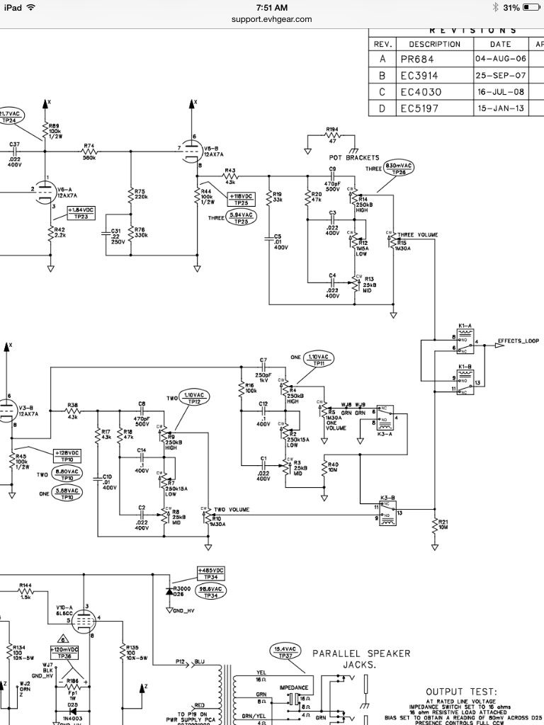
I can see a few reasons. The divider cuts both the signal and DC level from the prior anode (~50%). The schematic shows 128vdc on the cathode WITH the divider. That's already a fair amount of cathode to filament voltage. (That's assuming the filaments are referenced to ground.) If that divider were not there - you'd have ~200v on that cathode and that's over spec and a likely a point of tube failure. The signal cut and some HF roll-off due to C31 may be desirable too. Probably a combination of all of these are reasons for the divider to be there.
“If you have integrity, nothing else matters. If you don't have integrity, nothing else matters.”
-Alan K. Simpson, U.S. Senator, Wyoming, 1979-97
Hofstadter's Law: It always takes longer than you expect, even when you take into account Hofstadter's Law.
Looking at the Soldano slo schematic, the test point voltage at the grid of the CF shows 200v so it seems like that is okay. My circuit does have elevated heater voltages so maybe that has something to do with it.
One reason for the divider might be to increase the availabe signal amplitude (headroom). The cathode follower in the traditional configuration steals about 100V of headroom from the driving stage because grid current starts to flow in the follower if the plate to cathode voltage gets too low. The fix for this is to hot bias the driving stage to get some headroom back.
WARNING! Musical Instrument amplifiers contain lethal voltages and can retain them even when unplugged. Refer service to qualified personnel. REMEMBER: Everybody knows that smokin' ain't allowed in school !
It looks like the cap is added in there so that the AC and DC can have independent voltage dividers that result in different amounts of respective attenuation. That .22uF cap with those resistors calculates out to about a 1Hz break frequency. It is not there for "tone shaping"; it is essentially the AC signal ground. The DC voltage is reduced by about 50% but the AC voltage is reduced by just over 70%.
I didn't know some of the stuff the guys previously mentioned. Putting it all together, it seems like a pretty clever solution to some typical issues that allows independent flexibility of the AC & DC portions of the circuit. Something I'll have to try out in the future.
I'm getting the same 1hz using the filter formula and plugging in the 2 resistors. Weird thing is I took it out of the circuit and it seemed like it was brighter. Is there some others hidden impedance that needs to be accounted for in the formula? Or maybe the miller capacitance of the cf coupled with the 2 resistors changes the freq response?
Intuitively, I would expect it to appear to sound brighter with the cap removed. My guess it that it is related more to our ear's perception (Fletcher-Munson ear sensitivity curves, etc.) than anything. I kind of doubt that a bode plot of the frequency response would have a different shape; the whole thing would just be higher in amplitude.
That being said, you do also have to think about how the signal is affected by the driving impedance / capacitance of the preceding tube, miller capacitance at the grid of the CF and other subtle differences at the grid of the CF tube that can slightly alter the high frequency response as the grid leak resistor value (as seen by the AC signal) is changed. All told, it is probably still pretty subtle and probably difficult to show measured differences that add up to anything appearing significant (again, just intuitively guessing here - please correct me if you have actual experiential knowledge).
One reason for the divider might be to increase the availabe signal amplitude (headroom). The cathode follower in the traditional configuration steals about 100V of headroom from the driving stage because grid current starts to flow in the follower if the plate to cathode voltage gets too low. The fix for this is to hot bias the driving stage to get some headroom back.
So as the plate voltage of the common cathode stage becomes more positive wrt zero volts AC or quiescent DC, causing the cathode follower's cathode to become more positive the grid current from the cathode follower works against this positive swing causing non-linear performance? Do I have this right? So hot biasing moves the quiescent DC plate voltage to a more negative point thus increasing the plate to cathode voltage of the cathode follower (colder bias) for the entire swing? Do I have this right?
I think you do. I've been studying some more on this and what I'm getting is that the bias on these things is set by the dc voltage on the gate, so by the preceding stage unless there is a divider
 Tweet
Tweet

Comment