Ad Widget

Collapse

Announcement

Collapse
No announcement yet.

Gallien Krueger MB150 unpredictably unstable

Collapse
X
 
  • Filter
  • Time
  • Show
Clear All
new posts

  • Gallien Krueger MB150 unpredictably unstable

    Hi there. This nice old GK MB150e came in with a fuse blown, the complaint being it started humming then the fuse went. Two of the outputs were shorted. All other semiconductors beeped on the diode tester but I changed all the outputs (TIP35c/TIP36c) and the three drivers (TIP29c/TIP30c). I set the bias ( by watching the current draw 'knee' like Enzo taught me, and doing the fine adjustment for 0.6vDC on the output bases) having brought it up slow on the variac and it was fine at first, but the fault remained - after a short while it hummed (I presume stuck to a rail), the current draw shot up, then shorted just one output transistor - Q783 - before I could switch it off. Replaced all outputs and drivers all over again but this time also put a new heat transfer sheet (the grey stuff) under the outputs, just because I didn't the first time and you never know, that stuff has caught me out before. Up on the variac again and it ran fine for a while then the depressing thing that happens, happened - it hummed again, though my finger was on the switch and I switched it off quick and saved the outputs from shorting, though not I guess from stress. Turned it on again normally, with the switch, and with heart in mouth (actually I just thought, f*ck it, in for a penny), and it is running happily here beside me, but of course I can't really trust it enough to give back to the customer. I played it quite hard for a while - all still good.

    What would you do to ensure stability?
    Attached Files
    Last edited by Alex R; 02-26-2015, 04:05 PM.

  • #2
    I almost blew up a nice speaker cabinet and the outputs in a Kustom amp on my bench. I was troubleshooting for preamp noise and had one of the board modules out of the amp, BUT, because the grounds on this design are daisy chained on plug in cable jumpers I had inadvertently lifted the ground reference to the output module. If the amp you're working on has such connections you might check them for cleanliness/continuity, open or shorted cables or for any possible damage to board traces or cracked solder joints near those connections.
    "Take two placebos, works twice as well." Enzo

    "Now get off my lawn with your silicooties and boom-chucka speakers and computers masquerading as amplifiers" Justin Thomas

    "If you're not interested in opinions and the experience of others, why even start a thread?
    You can't just expect consent." Helmholtz

    Comment


    • #3
      I don't like that series of amps. Does yours have the original SMPS or the analog power supply?

      If it's the SMPS it may not like being brought up slowly with a Variac.

      Comment


      • #4
        no it's the analog psu

        yes the earths, sorry grounds, can cause such confusion, but I have them hooked up pretty secure. It is very clean in there, the grounds are very secure and doubled-up everywhere and the boards look like new. A well made traditional design is my impression.

        so frustrating when it won't display the fault, just makes you insecure that it might happen. What's really getting to me is the customer described just these symptoms - usually it ran ok, then started having brief spells of humming, then hummed and blew a fuse. If he takes it home and it happens again it's not really going to look like a fix to him is it . And in truth I don't know the cause.

        Comment


        • #5
          Originally posted by Alex R View Post
          no it's the analog psu
          Then I'd hook it up with a light bulb limiter and start flexing the boards, etc. to try and make it go into failure mode.

          The basic design of the amp is very straightforward, but the mechanical execution was problematic IMHO.

          Comment


          • #6
            Yup. What Bill said. It could still be an intermittent fault in a solder joint or component.
            "Take two placebos, works twice as well." Enzo

            "Now get off my lawn with your silicooties and boom-chucka speakers and computers masquerading as amplifiers" Justin Thomas

            "If you're not interested in opinions and the experience of others, why even start a thread?
            You can't just expect consent." Helmholtz

            Comment


            • #7
              Thanks guys. I get back in the shop on Monday morning and will put it on the limiter and knock it abaht a bit

              Comment


              • #8
                It might be a mechanical intermittent, test for it as suggested above.

                It might also be thermal instability, causing it to work reasonably in the Lab, but when subject to stage use runaway when beyond a certain temperature and bite you in the *ss.

                To test this, try to duplicate grueling live conditions.

                To begin with, suggested biasing as suggested in the schematic does not make me very happy: "15mV +/-10mV across 0.1 ohm emitter ballast resistors" means that bias is "acceptable" between 5 and 25 mV (a 5:1 variation !!!!! ) meaning 50 to 250mA per device meaning 2.25W to 11.25W per device or 45W idle dissipation counting all 4.
                That is CRAZY , the MB150 (of which i repaired quitre a few, including the pesky SMPS type) uses a passive, non fan cooled heatsink, which at those power levels will be hot, not just warm, idle !!!

                To play it safe, I suggest the following.

                1) adjust bias to a cold setting of 5mV across each 0r1 resistor

                2) inject your favorite frequency, 250 to 1000 Hz is fine, start rising volume until amp just clips, then back a little.
                Clipping actually cools the amp.

                3) use a large 4 ohms resistor, it will heat up a lot, I drop mine inside a 10 liter (2.5 gallons) plastic bucket of water, no kidding.

                4) measure the heat sink temperature with your trusty finger-o-meter, it will become unbearably hot in some 10/15 minutes.

                5) set volume to 0 so you have NO signal on the load and recheck bias ... it *should* be stable but don't be surprised if it drifts up ... that's exactly what we are checking.

                Readjust if/as needed to keep the 5 mV , then reapply signal and continue toasting it.

                6) if the amp is stable after 2 hours (it will be VERY hot) , personally I would trust it .

                I have seen pictures of Boutique amp builders (think Fuchs and other serious ones) with racks cooking , say, a dozen chassis overnight (8 hours) before delivery.

                Just don't leave it unattended, sh*t happens and it's better if you are not far away ... doing something else, of course.

                If you need to measure inside but the amp needs to be roughly assembled to test, tack solder a couple wires across one emitter resistor and bring it out to some convenient terminals or socket for measuring .

                Unless you have "claw" type spring loaded multimeter test leads and you leave them there all the time.
                Juan Manuel Fahey

                Comment


                • #9
                  You put your load resistor in a bucket of water?
                  Seriously?
                  Dude, get a bigger load resistor, or tie a few together.

                  Comment


                  • #10
                    Seriously.

                    in fact, it's the approved method to test large PA power amps.

                    There's no other way to dissipate 2 to 10kW .

                    It's also an OLD trick used to test RF power amps, transmitters, industrial RF heating stuff, etc.
                    Juan Manuel Fahey

                    Comment


                    • #11
                      I've considered building an indestructible dummy load from submerged water heater elements Except that I don't really have a use for it. Of course, Having a need for it isn't the entire reason for doing it You do that sort of thing because it's cool and you can. The trouble is that then I would REALLY want to find something enormous to plug into it!
                      "Take two placebos, works twice as well." Enzo

                      "Now get off my lawn with your silicooties and boom-chucka speakers and computers masquerading as amplifiers" Justin Thomas

                      "If you're not interested in opinions and the experience of others, why even start a thread?
                      You can't just expect consent." Helmholtz

                      Comment


                      • #12
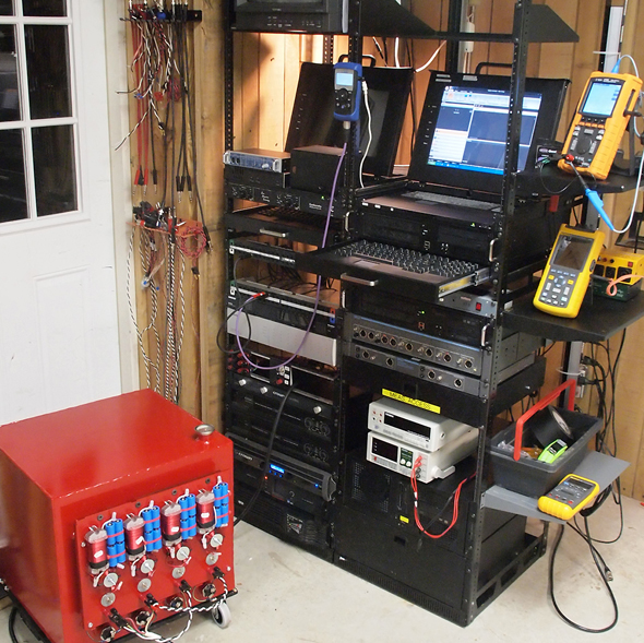
                        FWIW here's a Pro who built a 14 kW capable oil cooled 4 ohm load .

                        Big Dummy Load « Pro Sound Training

                        No need to drive them that high of course, here he shows tests with 1 kW .

                        The beauty lies in the incredibly good linearity and non-inductance measured:


                        Since you need more than a tree to call it a forest, here's another:

                        AV: Real World Testing: Matching Amplifier Data And Specifications - Pro Sound Web


                        Figure 1 shows “The Mother-Load,” a 4-channel by 8-ohm dummy load. There are four 1,800-watt water heater elements (purely resistive) that are mounted into a 25-gallon steel tank filled with environmentally-friendly mineral oil.
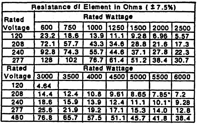
                        A handy table:

                        Juan Manuel Fahey

                        Comment

                        Working...
                        X