Hi, mr Printer! Yes, I saw your version everywhere I looked prior to my bringing my issue to this forum.
Fortunately, I only need one switch in one place.
You have many switches, and maybe people here will want to comment on your schematic!! I can't though. Your wonderful design can't help me at all because I don't understand that much yet :�(
Perhaps you would take the time to create an easily searched title and start a thread about your design on this forum and describe the switching features as well as a list of the part numbers and sources for these applications.
That would be very meaningful for people like me!!
Oh— leaving a link from that thread topic on this thread would be most appreciated too, printer!
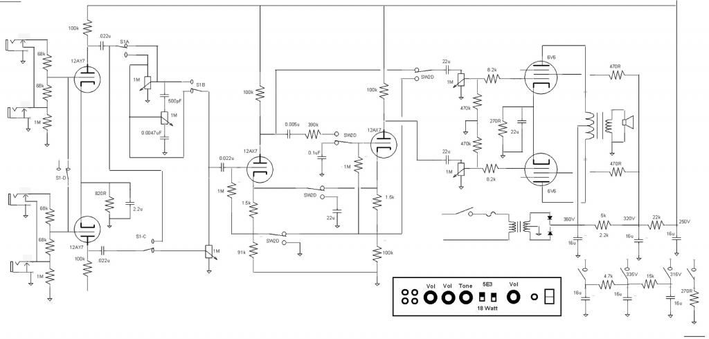
Nearly there; the wire from the 'cathodyne' side of the switch should connect to the 0Vdc 10M side of the 0.1uF cap, rather than the side that connects to the cathodyne grid.
Hi, mr Printer! Yes, I saw your version everywhere I looked prior to my bringing my issue to this forum.
Fortunately, I only need one switch in one place.
You have many switches, and maybe people here will want to comment on your schematic!! I can't though. Your wonderful design can't help me at all because I don't understand that much yet :�(
Perhaps you would take the time to create an easily searched title and start a thread about your design on this forum and describe the switching features as well as a list of the part numbers and sources for these applications.
That would be very meaningful for people like me!!
Oh� leaving a link from that thread topic on this thread would be most appreciated too, printer!
Only need a single switch for the PI circuit, a four pole switch.
Not a design you would want to do if you are not well versed in tube circuits. If you are not careful about the wiring you could get some interactions that you do not want. Spending most of my time learning to build acoustic guitars and while it was interesting coming up with different takes on some classic circuits it is not something I am all that interested in right now. Still have some designs I cooked up that I want to build, maybe after a few more guitars.
Thank you for going over my drawing above, Pete. Boy, that was a shot in the dark. haha!!
I decided to use a triple-pole/double-throw switch. Now the preamp signal is routed to either one of the PIs simultaneously with the target PI's dual outputs going to the pwr tube grids.
If I get thumps, I'll fiddle around with more 10M resistors~ haha!!
Looking good!
However, we should mitigate for an output pole of the switch going dodgy and leaving a power tube control grid open circuit (dc), with no grid leak.
From that, I think it would be best to put the 220ks directly between the grid s and ground, and replace the 4 x 220ks on your plan with 10Ms.
The input and output switch wiring should be kept apart as much as feasible, and maybe check that adjacent switch poles have opposing signal polarity.
It may only be a marginal or non existent benefit, but with reference to the input pole at the right hand side of the switch, the signal on the middle pole should be in opposing polarity and the left hand pole in the same polarity (as the input).
As a general principle, that thinking may help to ensure that if necessity does bring cascading stages in close proximity, then negative feedback (via capacitive coupling) should be a bigger factor than positive feedback.
The way you've drawn it looks like it conforms with the above.
As your arrangement is intended around unity gain, it's probably immaterial.
Thank you so much for looking over this process, Pete!
�the signal on the middle pole should be in opposing polarity and the left hand pole in the same polarity (as the input).
The way you've drawn it looks like it conforms with the above [Pete's comment on opposing signal polarity].
As your arrangement is intended around unity gain, it's probably immaterial.
 Tweet
Tweet
Comment