Announcement

Collapse
No announcement yet.

Single Rectifier - Burnt Resistors in V1 Preamp Stage

Collapse
X
 
  • Filter
  • Time
  • Show
Clear All
new posts

  • Single Rectifier - Burnt Resistors in V1 Preamp Stage

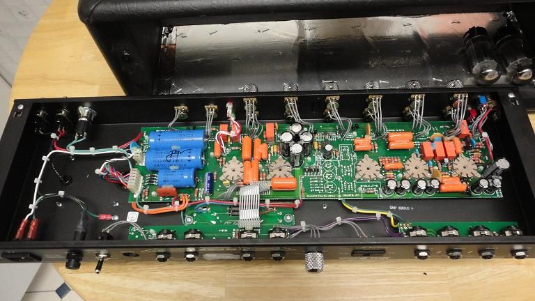
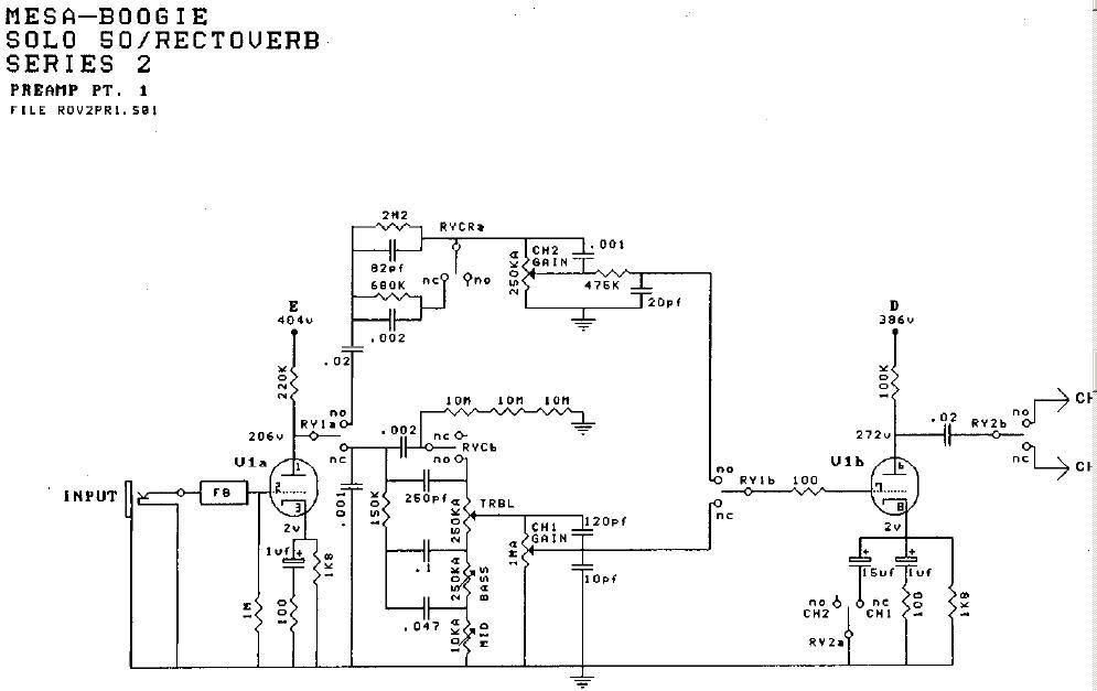
    Picked up a Mesa Single Rectifier Head today and need to make some repairs to get it working. I found the schematic here on the board which is great but it's not matching up with the circuit board.

    Can anyone tell me the value of the resistor in the middle? Are these all rated at 1W? Thank you!


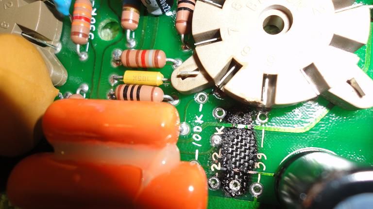
    After replacing the resistors I'm going to install all new tubes, including the power tubes which I found damaged and replace the 20A fuse that was incorrectly installed with the correct 2.5A. I'm guessing that the first stage V1 tube failed and since the incorrect fuse was installed it did not blow and therefore heated up the resistors and the power tube.
    Last edited by Engine09; 09-06-2015, 03:06 AM.

  • #2
    The resistors are 1/2 Watt rating.
    I don't have enough information from you to be able to figure out the value of the resistor that burnt. Post the schematic you have and show additional photos of the amp. That will help us help you.

    One important fact I can tell you is that the burnt part of the PC board is carbonized so much that it will be conductive which will be a problem. The remedy is to remove all the burnt part of the board. Usually this is done by grinding it away with a Dremel tool. At the very least you need to remove enough of the burnt part such that there is no continuous burnt material between any of the board traces or component lead holes. This could mean that some traces may need to be replaced with jumper wires.

    Comment


    • #3
      1/2W, got it!

      I have a lot of experience with circuit board repair, the pic was taken after only cleaning with alcohol. I'll be sure to clean a bit more, raise the new resistors a bit, use heatshrink, etc. Also have many different gauges of wire for any trace repair.

      Here's the schematic I'm working off, I just realized it has to be for the combo amps. I don't see any 100k, 22k or 39 Ohm resistors anywhere near V1, plus the tube in the schematic only has 6 pins.

      Thanks!

      My amp, Mesa Single Rectifier Solo Head 50W Series 2:


      Schematic:

      Comment


      • #4
        Originally posted by Engine09 View Post
        ... I don't see any 100k, 22k or 39 Ohm resistors anywhere near V1, plus the tube in the schematic only has 6 pins...
        The "22k" may be "220k" with the zero burnt off. I don't know what's up with the 100k and 39 markings.

        Regarding the tube pins. Only 6 pins are shown on the preamp schematic but the tube actually has 9 pins. #4,5 & 9 are the heater pins and they are often not shown. The heater pins are sometimes shown in the power supply section of the schematic.

        Comment


        • #5
          Originally posted by Engine09 View Post
          I have a lot of experience with circuit board repair, the pic was taken after only cleaning with alcohol. I'll be sure to clean a bit more, raise the new resistors a bit, use heatshrink, etc.
          So I hope that you know (just checking) that carbonized PC board is conductive and you have to remove the carbonized part. Otherwise, the amp will fail again very quickly.
          Originally posted by Engine09 View Post
          Here's the schematic I'm working off, I just realized it has to be for the combo amps.
          I think that you should post full schematic of the amp because, for example, the 39 Ohm resistor may be a part of the power supply circuit not shown on the partial schematic you posted.
          Originally posted by Engine09 View Post
          I don't see any 100k, 22k or 39 Ohm resistors anywhere near V1,
          I see 100k connected to anode of V1, I see 220k connected to second anode of V1, I see 39 Ohms resistor is the power supply. 22k is clearly 220k - look at the distance between "22" and "k".
          Originally posted by Engine09 View Post
          plus the tube in the schematic only has 6 pins.
          Are you sure? What about heaters (pins #4, #5 and #9 shown as usual with tube amps on another page of the schematic)?
          To identify the burnt out part you need to identify where it was connected. This could be the Zener diode from the power supply but I'm not sure. Your photos do not show required details.

          Mark

          Comment


          • #6
            Mark already spelled it out. You did not show the whole schematic. The last page is the power supply, and the 39 ohm resistors are for hum balance and they connect to the heater pins. The 100k and 220k are the two plate resistors.

            The burnt mystery resistor looks to me like it has a bit remaining of a link to the ground trace along the bottom. So the first thing I'd do would be measure resistance to ground from pins 3 and 8 of the socket to see if each still has the 1.8k cathode resistance. I'd not be surprised if one of them shows open. In the whole V1 circuit, I see no other resistors with much likelihood of burning up. And frankly, since 12AX7s don't as a rule short plate to cathode, I'd suspect what happened was an arc struck from something its traces passes near.
            Education is what you're left with after you have forgotten what you have learned.

            Comment


            • #7
              Perhaps this pic can be useful.

              Click image for larger version

Name:	recto.jpg
Views:	1
Size:	132.5 KB
ID:	839440

              Comment


              • #8
                It seemed 22K. It could be the one marked in this scheme. It is very easy to check if it is (connected to the first 220K plate resistor).

                Click image for larger version

Name:	ali.jpg
Views:	1
Size:	108.3 KB
ID:	839441

                Comment


                • #9
                  The 39 ohm resistors are for the DC Heater Filament voltages for V1.
                  +3Vdc & -3Vdc.

                  V1 DC Filament.pdf

                  Comment


                  • #10
                    Agree with Pedro, resistors in pic from post #1 should be 100K, 22K, 39ohm, 39ohm from left to right. (Markus, I think the space between 22 and K is because there is a solder point in there).

                    But can someone explain to me the 3rd band of the colour code? If it's a digit, shouldn't it be black in most cases (like the 100K in Pedro's pic)? Is the 22K 22.1K, or the 39 392? That's how I read them using standard 4 digit code.
                    Originally posted by Enzo
                    I have a sign in my shop that says, "Never think up reasons not to check something."


                    Comment


                    • #11
                      Most Mesa's use four digit code resistors.

                      The first three bands are value and the fourth is the multiplyer.

                      Comment


                      • #12
                        Yes, G1 you are right. The resistors are of 1% precision. 2+2+1+2 = 221*10E+2 = 22.1k. 3+9+2+0+1= 392*10E-01 = 39.2 Ohm. Typical 1% precision resistors.

                        Mark

                        Comment


                        • #13
                          I was stuck and not even thinking to look at the power section for pins 4, 5 & 9 of that tube, I see them now in the schematic section Pedro posted. Making much more sense now, thank you guys!

                          100k Ohm on the left, confirmed.
                          22k next, confirmed.
                          39 Ohm next, confirmed.
                          39 Ohm last, confirmed.

                          I keep on making a mistake reading the color code on the 39 Ohm resistor though.

                          Orange = 3
                          White = 9
                          Red = 2
                          Blk = Multiplier 0 (x1 - Add no zeros)

                          Why again is this 39.2 and not 392?

                          I'm going to make a mistake in the future if I don't figure this out.

                          And yes, I'll be cleaning up the board with a dremmel tool and most likely removing those 2 traces and repairing with jumpers. Will also raise the new resistors slightly off the board and use heatshrink on the leads if needed.

                          Comment


                          • #14
                            Originally posted by MarkusBass View Post
                            3+9+2+0+1= 392*10E-01 = 39.2 Ohm. Typical 1% precision resistors.
                            3+9+2+0+1 is five bands, not four. I don't see how you get the 10E-01 here.
                            My guess is that in Pedro's pic, those are 392R stuck in there and it doesn't really matter much.
                            Otherwise I'm just as confused about it as Engine09:


                            Originally posted by Engine09 View Post
                            I keep on making a mistake reading the color code on the 39 Ohm resistor though.

                            Orange = 3
                            White = 9
                            Red = 2
                            Blk = Multiplier 0 (x1 - Add no zeros)

                            Why again is this 39.2 and not 392?
                            Originally posted by Enzo
                            I have a sign in my shop that says, "Never think up reasons not to check something."


                            Comment


                            • #15
                              Four bands for resistance and one for tolerance, the last brown stripe for 1%. Five total. Your common three band code usually ha a fourth band for tolerance, dunnit?
                              Education is what you're left with after you have forgotten what you have learned.

                              Comment

                              Working...
                              X