Announcement

Collapse
No announcement yet.

Marshall JMP MKII non master volume

Collapse
X
 
  • Filter
  • Time
  • Show
Clear All
new posts

  • #16
    I (respectfully) disagree with Lowell on the voltages. In the post he responded to the bias voltage seemed grossly high and there was no drop across the choke where I would expect a couple of volts drop.

    Your bias is too cold.

    At 427Vp I would think that a bias voltage of about -45 would be about right for a pair of 6550's. No math on this though. Just my own experience. -40 for a pair of el34's.

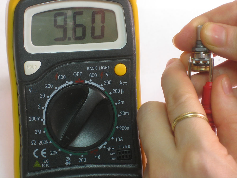
    Check DCR on the choke. I think it should be between 120 and 200 ohms. If it's not, it's shorted.

    That amp is OLD! There are parts that fail with age. As you've noted, the old caps have suffered. You've replaced a couple. CC resistors drift. Old electrolytic caps should be replaced. Those Xicons don't have nearly the lifespan of old school caps. They are critical components as bias supply caps. And they've been around long enough that they could absolutely be overdue for replacement. But if the bias is fine, and adjustable, I suppose it's probably ok for now.

    What is the bias current?
    "Take two placebos, works twice as well." Enzo

    "Now get off my lawn with your silicooties and boom-chucka speakers and computers masquerading as amplifiers" Justin Thomas

    "If you're not interested in opinions and the experience of others, why even start a thread?
    You can't just expect consent." Helmholtz

    Comment


    • #17
      Wow, I found a couple hair rising statements here.
      1)
      Pin(5) -069.5
      -69V bias on power tubes ... which was probably even worse, measuring straight at the socket the meter causes a voltage drop, so bias might have been as cold as -75 tom-80V . Ugh !!!
      No doubt the tubes were grossly cutoff, the amp worked in Class C (much colder than plain Class B) , sound is chopped and distorted in an ugly way, sounding like a horrible noise gate.

      2-3)
      -78.4v and -71.5v on the ground side of the cap
      What I imagined.
      Counts as Two because you can't have over 70V on the *ground* side of anything (unless it's disconnected, that is) , he means the *negative* side, not the same.
      Just a hint which should have helped: the positive side shows 0 Volts .... because that is the grounded side.
      I shudder thinking what would have happened if the "error" had been "corrected" by grounding the negative end of the cap.

      4)
      Found it, the 220ohm resistor in the bias circuit is junk
      I need some schooling now..although it is working, that 220 ohm resistor was reading correct..with it removed it works correct..I put a new one in and it's working fine. My question is how could the ohms be correct on that resistor but it still be bad? Is that possible?
      I see NO 220 ohms resistors in that picture, and nothing on it could hav e measured 220 ohms, so can you please point at them?

      You found, read, measured and replaced something I can't see.

      Applying Enzo's "horses before zebras" I'd suspect no voltage drop across choke being caused by cutoff tubes (given the other data present) before a shorted choke.

      Not that it's impossible, but having a gross symptom pointing at it, I'd rather check said symptom first.

      Doubly so because now "tubes are nice and blue" and amp is behaving properly.
      In fact, I guess NOW we'll have some voltage drop across the choke .

      Ok, all is well if it ends well
      Congratulations.
      Juan Manuel Fahey

      Comment


      • #18
        Just re-read that one... It says 220 ohm not 220k. Whoops.
        When the going gets weird... The weird turn pro!

        Comment


        • #19
          What I was looking for in the voltages was a 0V screen voltage or negative bias voltage missing. Anything OBVIOUS. I then suggested the bias be checked. My bad for saying they looked fine...I was just working towards the same thing through a different route. I generally dont care what the negative bias voltage is and depend more on the actual current. Sorry for the confusing reply.

          Comment


          • #20
            To the right of the bias wheel behind the diode is a resistor that somebody has just cut the old one out and soldered a new one in, it measured exactly 220ohms, the part info on the circuit board there says 220ohm as well.
            I didn't replace those 10uf caps someone else has already been inside of it, they had those clipped and snipped also and I put them back in correctly. There are still more resistors that need to be repaired/replaced that has been clipped and soldered on the top as well. I should have been suspicious of that resistor fom the start due to the solder job, cold solder just didn't cross my mind, guess I had stared at it to long yesterday!! But it sounds killer now! I'll check the bias out this evening and post back. Thanks again everyone

            Comment


            • #21
              Good to see you got it sorted overnight, what a team! Those output tubes were ice cold bias, no wonder the amp sounded awful. I bet it sounds like it ought to now, rip roaring proper-like.

              Lowell's observation that bias current is what's important, not so much the voltage, yes that's a hard learned lesson took me a while to figure out early in my amp wrenching career. Still a good idea to measure bias voltage once a proper bias current is set, just to make sure it's in line with expected range of values, and it usually is. Once done I stick a paper tag inside the chassis with date, bias current, bias voltage, hi voltage w/ no signal, hi voltage at clip, & power level at clip so next time if there's any major changes or even normal wear, the previous measurements are ready at hand to compare.
              This isn't the future I signed up for.

              Comment


              • #22
                Originally posted by pnut5150 View Post
                To the right of the bias wheel behind the diode is a resistor that somebody has just cut the old one out and soldered a new one in, it measured exactly 220ohms, the part info on the circuit board there says 220ohm as well.
                In both pictures, to the right of the bias wheel, between the blue capacitor and the 4 main rectifier diodes, there is a 5th diode with a resistor in series, below it.
                As clearly seen on the picture, it's a 220k=220000 ohms resistor, red-red-yellow , 2-2-0000 ohms, NOT 220 ohms , red-red-brown , 2-2-0 .


                Anyway, if you had read the colours wrong (I myself sometimes have it hard to pick red or orange on some brownish background resistors) but the meter should have shown the value in big bold numbers.

                Yes, the display certainly read "2-2-0" because it has 3 or 4 digits, not 7 or 10 nor whatever is needed, like in handwriting or printing, that's why the selector wheel changes the *scale* which in this case must have been the "2M" one, meaning the maximum value which can be displayed is 1.990 meaning 1.99 Megohms.

                In that scale you must certainly read "2-2-0" , no doubt, but you must add 3 zeros to the right, because the display does not have 6 digits to show them.

                And how do you know how many zeros to add?
                That's what the scale indication is for.

                In this example (sorry, I use the image I can find)

                the number displayed is 9.60 .
                Does it mean it's plain 9.60 ohms?
                No, look at the scale being used, it can display up to 19.99 meaning 19900 ohms,conventionally called 20000 ohms, thus the "20k" (20000) name printed there.
                So if maximum "displayed number" possible is 19.99 (19900 ohms) , then "9.60" actually means 9600 ohms .

                So I *bet* your display read "220" which you wrote literally, but multimeter was on the 2M scale, which you didn't specify , confusing us.
                Worse, you claimed it was plain "ohms" while the scale was actually "thousands of ohms" .

                Just curious: do you have an autoranging multimeter?

                Those "help" you by automatically changing scale without your intervention, a mixed blessing because sometimes if you are in a hurry or worried they can cause this kind of confusions.

                EDIT: and I'd love to see what's actually printed on the PCB, I bet it's 220k and not 220 .
                Last edited by J M Fahey; 09-13-2015, 02:32 PM.
                Juan Manuel Fahey

                Comment


                • #23
                  Originally posted by pnut5150 View Post
                  To the right of the bias wheel behind the diode is a resistor that somebody has just cut the old one out and soldered a new one in, it measured exactly 220ohms, the part info on the circuit board there says 220ohm as well.
                  I didn't replace those 10uf caps someone else has already been inside of it, they had those clipped and snipped also and I put them back in correctly. There are still more resistors that need to be repaired/replaced that has been clipped and soldered on the top as well. I should have been suspicious of that resistor fom the start due to the solder job, cold solder just didn't cross my mind, guess I had stared at it to long yesterday!! But it sounds killer now! I'll check the bias out this evening and post back. Thanks again everyone
                  So it was a 220k resistor and it was the exact resistor I couldn't take my eyes off looking at your picks. It looks like a pain in the butt trying to get that board out and I can see why people do stuff like soldering new components to snipped legs on the top side of the board. Sometimes troubleshooting an amp means first getting the amp back to normal.
                  When the going gets weird... The weird turn pro!

                  Comment


                  • #24
                    Originally posted by J M Fahey View Post
                    Anyway, if you had read the colours wrong (I myself sometimes have it hard to pick red or orange on some brownish background resistors) but the meter should have shown the value in big bold numbers.
                    Indeed I've seen some 100K carbon comps where the yellow band looks brown. "When in doubt, whip the ohmmeter out." And I've mentioned my competitor who either is color blind or works in the dark, can't tell brown from red, puts 4700 ohm resistors on Fender screen grids, too lazy to check with a meter... also charges a fortune for his "work." As long as he keeps it up I'll always have work.
                    This isn't the future I signed up for.

                    Comment


                    • #25
                      I have a '73 MKII, model 1987 50watt like yours.
                      Killer sounding amps worth some good $$$ so you may want to do a good pro job with good quality parts if it's yours.

                      The US models came with 6550's, I set mine up for EL34's, changing the bias feeds from 150k to 220k etc.

                      Comment


                      • #26
                        Originally posted by drewl View Post
                        I have a '73 MKII, model 1987 50watt like yours.
                        Killer sounding amps worth some good $$$ so you may want to do a good pro job with good quality parts if it's yours.
                        True 'nuff! I owned 2 and sold 'em both for $600 each mid 90's. One buyer whined that I was skinning him, baloney he could well afford it and it's a terrific sounding amp that only climbs in $$ value. Funny thing actual power was only about 30 watts with a 400V B+ rail but oh what a tone! And loud enough for any reasonable purpose.
                        This isn't the future I signed up for.

                        Comment


                        • #27
                          BS thirty watts, unless you had a jtm45.

                          Even with the lower HV, these amps are rated at50w clean, mine puts out around 75w max.

                          Just like the 1959's that put out almost double their 100w rating.

                          Comment


                          • #28
                            Well, guess I jumped the gun..apparently last night at 2:00am I was seeing properly. Seems I didn't have the resistor soldered in good..I just tacked it in where they had already temporary..tonight I put it back in correctly and it was back to sounding terdy..with the resistor removed amp sounds fantastic..but tubes are as you guessed red plating. If I touch that resistor while amp is on with my soldering iron I get an arc and the amp plays normal for a second..HELP😁

                            Comment


                            • #29
                              Originally posted by pnut5150 View Post
                              Well, guess I jumped the gun..apparently last night at 2:00am I was seeing properly. Seems I didn't have the resistor soldered in good..I just tacked it in where they had already temporary..tonight I put it back in correctly and it was back to sounding terdy..with the resistor removed amp sounds fantastic..but tubes are as you guessed red plating. If I touch that resistor while amp is on with my soldering iron I get an arc and the amp plays normal for a second..HELP��
                              I was in question about replacement of the "220 ohm" resistor. Doing that would skew the voltage divider terribly and result in very high negative bias voltage (too cold). The sort of normal sound with the resistor removed is the result of NO BIAS VOLTAGE!!! Which might explain the red plates That the tubes aren't blowing up is a mystery to me. There may yet be a mistake in the soldering/wiring that has SOME bias voltage present somewhere (perhaps even on the cathode circuit). Try putting a 220k resistor in where you tried the 220 ohm previously. Then check bias current and voltage. Getting the bias corrected seems to be where you're problem is. Getting the bias circuit corrected is the first order of business then.
                              "Take two placebos, works twice as well." Enzo

                              "Now get off my lawn with your silicooties and boom-chucka speakers and computers masquerading as amplifiers" Justin Thomas

                              "If you're not interested in opinions and the experience of others, why even start a thread?
                              You can't just expect consent." Helmholtz

                              Comment


                              • #30
                                Sorry for the confusion..I did use 220k ohm resistor

                                Comment

                                Working...
                                X