Announcement

Collapse
No announcement yet.

More fun with scope image interpretation

Collapse
X
 
  • Filter
  • Time
  • Show
Clear All
new posts

  • More fun with scope image interpretation

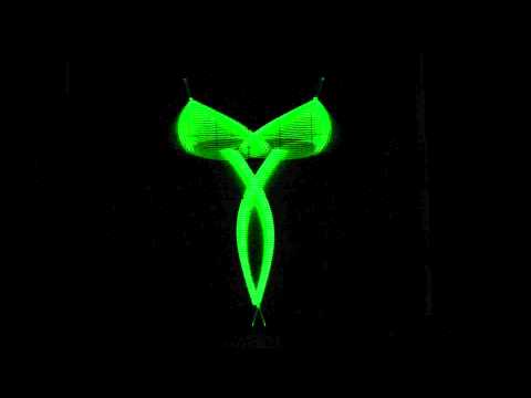
    I have an Ampeg SVT II with very strange looking output. I haven't really checked out the amp yet, but was wondering if anyone would care to comment on this funny looking output, or if they have seen similar before. From a quick look it seems screen grid resistors for power tubes are totally wrong, 220K. The schematic I have lists 22 ohms for screen grid resistors for 6550s. maybe there are many problems. This one had been at a shop for about a year, now I have it. just about to get into it.

    Here's 1K

  • #2
    100Hz gets really weird

    Comment


    • #3
      That looks like higher output than the 1K, if you reduce the volume, does it change? Is that just ugly clipping?
      For the resistor, did you check with your meter, and it's 220K not 220 ohm?
      Originally posted by Enzo
      I have a sign in my shop that says, "Never think up reasons not to check something."


      Comment


      • #4
        Originally posted by nsubulysses View Post
        100Hz gets really weird
        There's a clear hum problem in both cases. Perhaps if you fix that first then we can peel to the next layer of the onion. Or skin the zebra? Whatever.
        Experience is something you get, just after you really needed it.

        Comment


        • #5
          Start by using proper screen resistors, 220k is a mess.
          As is, it's worse than if it were triode connected, where at least screens tied to plates contribute their own current, here screens "cheat" the tube by showing some voltage at idle, which drops catastrophically when driven, so no surprised at wonky clipping.

          After that, retest, and also measure and post output voltage into the load.
          And update the YT screen capture
          Juan Manuel Fahey

          Comment


          • #6
            The reason I asked to veryify that they are 220K and not 220R, there was an update (they were changed from 22R to 220R).
            So check that they are actually not 220 ohms with your meter.
            Or perhaps someone tried to do the update, and put in 220K instead of 220R.
            Originally posted by Enzo
            I have a sign in my shop that says, "Never think up reasons not to check something."


            Comment


            • #7
              The schematics show 22 Ohms grid resistors but there was Customer Service Bulletin that suggested changing them to 220 Ohms. Someone tried to change the resistors but he put 220k instead of 220 Ohms.

              Mark

              Comment


              • #8
                Ok, I have changed screen grid resistors to 220R, they were indeed 220K. I know it's hard to see in the earlier vids but it says RMS and pk-pk in the bottom left of the screen in yellow writing. Before I was only getting about 5V RMS into a 4 ohm load. So yeah, about 6W....... screen voltage was about 190V. Now it's about 305V.

                I can get into the low 30's VAC RMS now for output, so creeping closer to 300W, but still looks terrible. I have a few better vids sorry for the shakiness of the earlier ones. The annoying sound in the background is the fan.

                1K Hz


                I read 21VAC on pin 4 of the output tubes at idle. Anode VAC is only 3.5V; control grid is about 1.5VAC.

                Had to switch some resistors in the bias supply back to stock. They had been changed to try to re-bias and make it work with the 220K grid resistors

                Will get back tomorrow. You can see this ripple/modulation easily in the 12AX7 that drives the 12AU7s for the phase inverter.

                Thanks for the comments so far.
                Suppose I should throw this up in case anyone wants to peruse -- Ampeg SVT-II Schematics.pdf

                I would be inclined to start looking around the C8-C11 section unless anyone there is something else that sticks out.
                Last edited by nsubulysses; 09-16-2015, 05:23 AM.

                Comment


                • #9
                  100Hz is just out of control

                  Comment


                  • #10
                    As nickb suggested I also think that there is excessive 60 Hz or 120 Hz ripple on the output signal. I suggest that you measure the B+ power rail ripple. Also slow down the scope sweep speed and the envelope of the ripple may then be apparent. (Just a different view of the signal.)

                    Comment


                    • #11
                      What is the input signal voltage?

                      Have you scoped the signal generator by itself lately to check wave form integrity?
                      "Take two placebos, works twice as well." Enzo

                      "Now get off my lawn with your silicooties and boom-chucka speakers and computers masquerading as amplifiers" Justin Thomas

                      "If you're not interested in opinions and the experience of others, why even start a thread?
                      You can't just expect consent." Helmholtz

                      Comment


                      • #12
                        Originally posted by Tom Phillips View Post
                        As nickb suggested I also think that there is excessive 60 Hz or 120 Hz ripple on the output signal. I suggest that you measure the B+ power rail ripple.
                        He said idling he had 21VAC on the screens, but only 3.5VAC on the plates.

                        Edit: he also said 1.5VAC on the grids, so that doesn't sound good.
                        Originally posted by Enzo
                        I have a sign in my shop that says, "Never think up reasons not to check something."


                        Comment


                        • #13
                          Originally posted by g1 View Post
                          He said idling he had 21VAC on the screens, but only 3.5VAC on the plates.
                          Edit: he also said 1.5VAC on the grids, so that doesn't sound good.
                          I see that now back in post #8. If those measurements are as stated then the screen and grid supplies need to be fixed before proceeding. What is the frequency of the AC on the screens and grids? Unless the measurements are a mistake there is something seriously wrong with the supply lines.
                          Last edited by Tom Phillips; 09-16-2015, 06:43 PM. Reason: Typo repair

                          Comment


                          • #14
                            Yeah I have to get back to this tonight if I have time. I probably will. Kind of a drag to be squeezing in an hour here and there on such a beast of an amp but oh well.

                            I will check the power supply caps and frequency of AC and all that and get back.

                            Input signal voltage is about 300mV pk-pk for 1KHz and 100Hz.

                            I'll try my other signal gen tonight when I get back to it too just in case. I don't htink it's that though, since this big modulation is only becoming visible in the output section.

                            Comment


                            • #15
                              unrelated but you guys have seen this Austrian guys oscilloscope art right?

                              pretty cool, the 'shrooms look just like the Liberty caps (Psilocybe semilanceata) found in my state (I'm told)
                              (until they built that Mormon Temple in Lake O...drats!)

                              Comment

                              Working...
                              X