Announcement

Collapse
No announcement yet.

Sunn 1200S Restoration project

Collapse
X
 
  • Filter
  • Time
  • Show
Clear All
new posts

  • Sunn 1200S Restoration project

    I recently took in a Sunn 1200S Guitar Amp to restore. This one has date codes inside and out back to arly 1969 (4-section Cornell-Dublier Cap Can, still has the Dynaco name stamped into the can). I’m just at the starting gate on this project, and have ordered replacement caps, power resistors grounding jacks and other such items for it.

    I did take the time to slowly bring up the AC mains on it, over the course of a day, using a solid-state 5AR4 replacement module to apply the FW rectifier output to the main caps., all tubes removed. Looks like there’s leakage current flowing in at least two sections, as I’m getting around 8mA current flowing thru the resistive string. The last section has about 500uA current flowing into the cap. Not surprised, with a date code of 6912….over 45 yrs old.

    But, it was low enough to chance powering up one pair at a time of the Tung Sol 6550 power tubes. Plate current ranged from 14, 15, 18 & 21mA in pairs, with plate voltage at 545V, using one of the 5AR4 rectifier tubes. I haven’t resumed any of the electrical check-out today, taking the time instead to photograph the unit inside and out.

    Early version of the 1200S, lacking the switched grounding input jacks, and having only one slide switch, labeled Mid-Boost. All I’ve done so far is replace the AC mains cord & fuse post, eliminating the Ground Reverse cap associated with the 2-wire power cord as it was built back then.

    All the grounding throughout this amp is done thru riveted terminal strips, with the HV Secondary C/T getting to chassis thru one rivet, while the negative terminal of the first 20uF/600V cap getting to chassis a few inches away. With all the metal corrosion I see on the outside, and 45 yr old rivet, I don’t’ trust any of that for grounding. Already some signal path to chassis exists between the cap-can ground and the initial charging current of that 600V cap. So, that ought to be fun.

    Click image for larger version

Name:	Chassis-Outside-1.jpg
Views:	1
Size:	248.7 KB
ID:	870088 Click image for larger version

Name:	Chassis-Outside-2.jpg
Views:	1
Size:	259.2 KB
ID:	870089 Click image for larger version

Name:	Chassis-Outside-3.jpg
Views:	1
Size:	240.5 KB
ID:	870090 Click image for larger version

Name:	Chassis-Outside-4.jpg
Views:	1
Size:	239.3 KB
ID:	870091

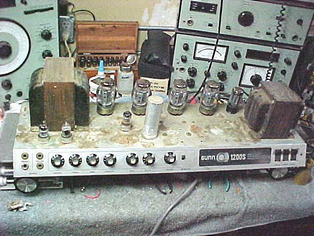
    The inside metal surface seems to be free from the corrosion that’s intense on the outside. Looks like a plating on the steel, like maybe Maganese or Zinc Phosphate, though I really don’t know. If time and cost weren’t an object, I’d gut the chassis and send it out to have it sand-blasted, and then treated, before re-building again. I’ll have to wing it as is, so open to suggestions.

    Click image for larger version

Name:	Chassis Inside -1.jpg
Views:	1
Size:	259.3 KB
ID:	870092 Click image for larger version

Name:	Chassis Inside -3.jpg
Views:	1
Size:	281.0 KB
ID:	870093 Click image for larger version

Name:	Chassis Inside -5.jpg
Views:	1
Size:	297.2 KB
ID:	870094 Click image for larger version

Name:	Chassis Inside -7.jpg
Views:	1
Size:	279.8 KB
ID:	870095

    I’ve tried a small area of the top corner using a product called ‘sandflex’, available in coarse, medium and fine grit embedded throughout the rubber compound block. I’m sure it will break thru the original coating, but as you can see from the photos, that coating is ancient history. I’m open to suggestions on the outside surface, besides this approach.

    Both transformers are quite rusty. I thought of using WD-40 in the process of working thru the rust, but perhaps there’s a better solution? I’m all ears.

    I haven’t yet assessed the tube sockets’ contacts. While they are lacking the usual flange-mount, using instead a locking snap-ring to hold them into the keyed hole, the contacts ARE fully circular, rather than the forked type, so that’s encouraging.

    The Reverb unit is a Gibbs tank, having a locking mechanism that I restored. Similar in DCR in/out to an Accutronics 4AB3C1B as we find in Fender Twin’s. It mounts to the inside roof of the cabinet, so hum coupling is no doubt an issue.

    Click image for larger version

Name:	Gibbs Reverb Tank-1.jpg
Views:	2
Size:	248.2 KB
ID:	870096
    Logic is an organized way of going wrong with confidence

  • #2
    What a project! Similar to a Sunn PA 120 I fixed up a couple years back.

    Good to not trust those riveted grounds. Unless it's verboten, mount some fresh grounding tabs with nuts n bolts, you may need to drill a couple holes. Good to scrape the chassis surface with mini wire brush or 400/600 grit at those points for best contact.

    Transformer rust, best solution is the laziest. Leave it be. Wire brushing, sanding, you take a chance on shorting laminations to each other with metal splinters. Soak with oil, no I wouldn't. If you must, paint for looks, so what if it's a little bubbly.

    Might be an idea to put in a second bias control, group the low 6550's one side & the higher reading ones on the other. About 35 mA per tube oughta do it.

    On the PA120, we wound up with solid state rectifiers (why beat up valuable Bungle Boy GZ34's?), KT88 JJ outputs, and it turned out a clean 120 watts @ clip, maybe not hi fi but good for any instrument amp or PA, 40 - 10KHz at full power. But who's so concerned about 20-20K at full rip? Better bandwidth at lower power, after all the power is Dynaco Mk III with doubled up output tubes. A couple of these, one just running power amp, thru a pair or quad of Altec A7's, there's enough for an old fashioned rock concert. Wear your bell bottoms, nehru jacket, love beads & mood ring, that's a show!
    This isn't the future I signed up for.

    Comment


    • #3
      I was also thinking about adding a second bias pot for that same reason. Good points made on the transformer laminations. I tried a little WD-40 on a rag on the end bells, and that seemed like it wanted to help. I haven't yet powered it up with all four 6550's in it, and bump the bias up to nominal level....see what the supplies look like then. In this amp, and all the other variants of the 1200, the O/T is powered AFTER the choke (both are in parallel). I'll no doubt end up with a bit more capacitance on the first stage, series-connected caps & ballast across them.
      Logic is an organized way of going wrong with confidence

      Comment


      • #4
        Years ago my bassist found a 2000s in the trash he gave me.
        I rebuilt it like you, only needing filter caps and output tubes.

        I cleaned up the rusty transformers and painted them.
        Mine was a transitional model with sockets for the rectifier and also had the plug in solid state rectifier.

        I used it as a practice amp at our studio for years then took it to a friends store to sell it.

        Someone from Sweden bought it and a huge matching cabinet someone else was selling. Shipment by boat was as much as the pair!

        Comment


        • #5
          Originally posted by nevetslab View Post
          In this amp, and all the other variants of the 1200, the O/T is powered AFTER the choke (both are in parallel). I'll no doubt end up with a bit more capacitance on the first stage, series-connected caps & ballast across them.
          That "pre filter" is standard issue on Dyna MkIII. Sunn licensed the design & bought a lot of their iron from Dynaco. "Why engineer a power amp when there's a perfectly good one." Worked out OK for both parties. On the PA 120 I did replace can caps with a pair of 50+50uF/500V in series, balancing R's, as I've seen practically all the old Dyna caps fail, why invite a sure fire disaster. Caps further down the chain, replaced with singles, and the one handling preamp grounded locally in the preamp zone. It's a big project, you just chip away one bit at a time, enjoy the improvements as you go.

          20 years back I thought I could get a pinch more power out of Dynaco MkIII by skipping the pre filter & running the OT center tap from raw hi voltage as it's typically done. Didn't work so well. Passing a sine wave thru, it developed a "point" as power approached clipping, as if the load was insufficient for the OT tap. And I heard that as distortion. So I put 'em back to normal. Some things, you can't improve.
          This isn't the future I signed up for.

          Comment


          • #6
            Originally posted by nevetslab View Post
            … Both transformers are quite rusty. I thought of using WD-40 in the process of working thru the rust, but perhaps there’s a better solution? I’m all ears…
            The rust itself does not cause a huge problem but it is sure unsightly. A treatment that works well for me is to remove loose rust particles and then apply a rust conversion coating. The attached photos show an amp before and after the transformers received this treatment.
            Click image for larger version

Name:	Jon1-004F.JPG
Views:	1
Size:	210.9 KB
ID:	840108 Click image for larger version

Name:	Jon1_3762.JPG
Views:	1
Size:	2.50 MB
ID:	840109
            For an even better look, follow with a coat of black paint. There are several rust conversion products on the market. One example is Corroseal. (See Corroseal Rust Converter | Metal Primer | Rust Paint)

            Comment


            • #7
              A big amp like this really should have power transformer secondary side fuse protection snuck in somehow. Given the bias tap, any B+ related fuse protection would need to be in the HV winding arms, not the CT.

              As well as an extra bias control - it would be best to make the pot wiper fail-safe.

              A smattering of grid stoppers in stages that can be overdriven may be noticeable, and the PI may need to be checked for cathode-heater stress at turn-on.

              Comment


              • #8
                I had a run of Sunn knobs made for me by Rogan the original supplier. Let me know if you need any.

                Comment


                • #9
                  Some excellent suggestions made from all of you. Adding the HT fuse protection sounds like a good idea, plenty of room for that.

                  On the PI cathode-heater stress at turn-on, what are you looking for? Is this specific on the 6AN8 Pentode/Triode tube? The three 6AN8 tubes I have are RCA's, two rescued from de-commissioned old test gear, the other from the 1200S. Of course, that tube socket is underneath the forest of circuit components of those two stages.

                  Click image for larger version

Name:	Chassis Inside -16.jpg
Views:	1
Size:	305.5 KB
ID:	840125

                  I had removed the Sunn knobs, dropped them into my ultra-sonic cleaner, dish-washing soap, ran them for 1/2 hr. Cleaner, though the white ink in some numbers are well faded, and all of the metal dress inserts have corrosion spots, so I would be interested in a fresh set. 'gbono', I'll send you an email on that.....many thanks!

                  Click image for larger version

Name:	Chassis-Outside-10.jpg
Views:	1
Size:	209.2 KB
ID:	840124

                  While I did order a fresh 4-section cap-can 30-20-20-20 @ 525V, I'll end up using that for the PI/reverb Driver/Preamp stages, and go with the series-stacked axial lead caps with ballast on the pre/post choke filter stages. Takes all the high charging currents out of the cap-can that does the damage, as well as dropping the supply potential. I also noticed in this early build, the preamp stage and pre-reverb tank drive stage are NOT wired to the final filter stage (10k to 20uf/525V filter cap).

                  10k grid-stoppers on the power tubes, at the socket pins directly where it should be. Interesting wiring arrangement on the two sets of power tubes. Each pair of tubes is upper/lower, with the second pair fed from the terminal strip containing the plate and screen resistors and lead-wires connecting those from the resistors. V4-V5 & V7-V6, where V4 & V6 are upper pair, V5/V7 are lower pair. Also noticed a 700 ohm load resistor to ground off the 16 ohm tap, and, on the schematics I have, it shows the SPKR jack is 16 ohm, and plugging into the EXT Jack, it/both become 8 ohm load, with the 4 ohm tap not being used. This looks to be wired with the tap not being used (Yel wire), though still connected to the 700 ohm load, and the impedance switching being between the 8 and 4 ohm taps, as seen in the images below (16 ohm YEL, 8 ohm WHT, 4 ohm BRN, Gnd BLK.

                  Click image for larger version

Name:	Chassis Inside -31.jpg
Views:	1
Size:	237.2 KB
ID:	840119 Click image for larger version

Name:	Chassis Inside -22.jpg
Views:	1
Size:	238.1 KB
ID:	840120

                  Seen along side the 700 ohm load resistor is the 1k/750pF feedback network to the tapped cathode resistor string of the 6AN8 Pentode input stage of the power amp.

                  I added the 2 Sunn 1200 & 1200S schematics I have, along with a Sunn Dual Rectifier Amp schematic, it being a PA amp (Sun 120?). None show the power supply wiring as it's built in this amp I have on the bench. Only one 600V cap, followed by the chokes and then into the 30-20-20-20 cap-can, with the last section not connected to the preamp stages.
                  Attached Files
                  Last edited by nevetslab; 11-19-2015, 07:56 AM. Reason: added photo of 6AN8 circuit component/build
                  Logic is an organized way of going wrong with confidence

                  Comment


                  • #10
                    A hazard that can arise with direct coupled stages is during startup, when V2 is not conducting and hence the grid of the cathodyne is effectively at B+. As well, the cathode of the cathodyne will be at ground. That has been known to cause arcing - and a grid-cathode diode can alleviate that.

                    Comment


                    • #11
                      Nice.
                      I just used Fender numbered knobs, close enough.

                      Comment


                      • #12
                        Never did understand why Sunholm used the 0-10 numbering. I guess you get "11" spaces while Fender knobs were only 10

                        Comment


                        • #13
                          So that would be one louder?
                          Originally posted by Enzo
                          I have a sign in my shop that says, "Never think up reasons not to check something."


                          Comment


                          • #14
                            The Dynakit preamp that Sunn started with had Rogan knobs but they were tan colored with just a triangle pointer. Sunn used an identical black knob with numbers on the front panel for a couple of years, then changed to numbers on the skirt. Gibson used Rogan on some years except they were grey. Music Man used Rogan knobs with a different font for the numbers.
                            WARNING! Musical Instrument amplifiers contain lethal voltages and can retain them even when unplugged. Refer service to qualified personnel.
                            REMEMBER: Everybody knows that smokin' ain't allowed in school !

                            Comment


                            • #15
                              gbono,
                              I sent you a PM yesterday.

                              Thanks!
                              66tele

                              Comment

                              Working...
                              X