 Tweet
Tweet
Dear all,
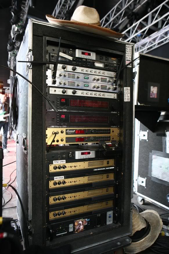
I've just receipt a broken Marshall 8008 paid 25 euros and I would like to tweak it to find how can I like it, but solid state power amp are not exactly my main field of knowledge.
Please correct me and/or integrate what I'm missing.
This is the schematic: http://www.drtube.com/schematics/marshall/8008.pdf
- C2 R2 and R1 make a highpass at 18 Hz;
- C1 and R1 make a lowpass at 10260 Hz;
- C3 and R3 make a lowpass at 4800 Hz and set the gain together with previous network;
- C13 and R9 make a hifhpass shelving at 7200 Hz together with the TR7 and TR16 network;
- D2 D3 R27 are a safety system for TR7 and TR16;
- TR7 and TR16 drive the following HT supplyed power stage by the dual 15 V supply;
- R45 is a sort of feedback, I guess;
- TR2 and TR10 drive the power stage;
- R24 R25 and TR5 are an amplified diode;
- TR1 and TR14 are the output transistors;
- R13 and TR6 plus R34 and TR15 seems something like a compressor, a variable voltage divider that limits the pilotage of the power transistors as they increase the voltage swing;
- C22 and R59 are the zobel filter;
But then...
- C19 R57 and R58... the cutoff frequency is 2 Hz, so what's its purpose? Why not just a resistor?
- R55 is in parallel with R57 and R58, again why?
- how the CFB and VFB works exactly?
Can anyone please help me?
I would like to adjust the response of this poweramp to my tastes, and with tube amps I know how to do it, while with this amp there are few points I'm missing.
Thank you all in advance.
Roberto


Comment