Announcement

Collapse
No announcement yet.

pignose 30/60

Collapse
X
 
  • Filter
  • Time
  • Show
Clear All
new posts

  • pignose 30/60

    hi.
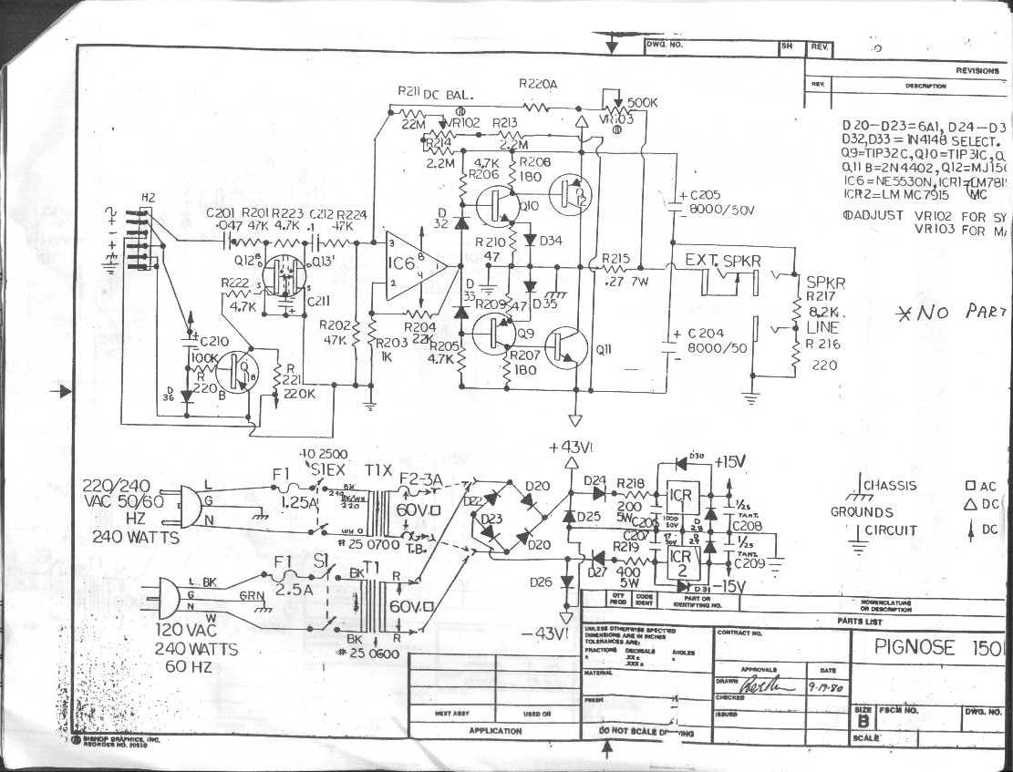
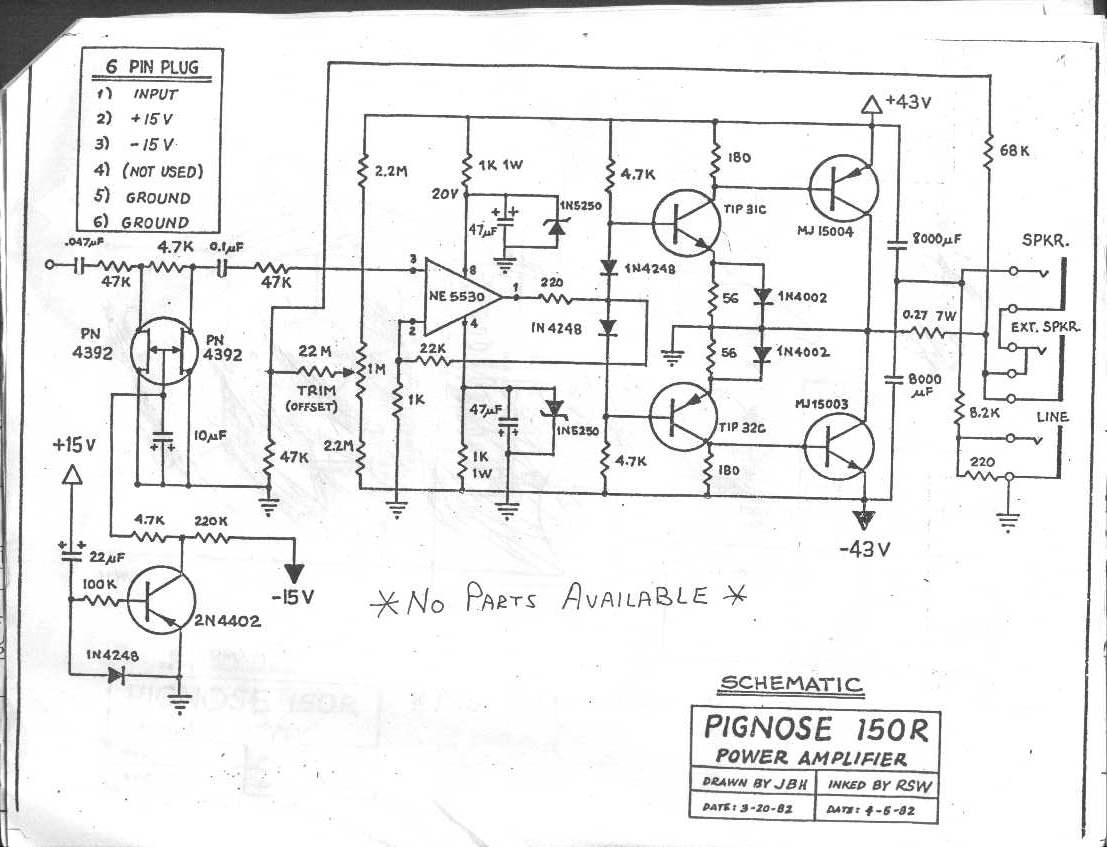
    Does anyone have a schematic of a pignose 7-3060 amp.
    i have one to repair but not sure if it has correct components looks like been repaired a few times before and some strange transistors, the output stage has 2n6031 and 2n3055 but they are not really a complimentary pair, should be either mj2955 with the 2n3055 or a 2n5631 with the 2n6031,
    thanks
    Dennis

  • #2
    You might try them directly.

    Contact Us ? Pignose Amps
    "I took a photo of my ohm meter... It didn't help." Enzo 8/20/22

    Comment


    • #3
      Used to have it many hard disk crashes ago; if I find it, i'll post.

      That said, 2 details:
      1) I seem to remember that output rail (transistor collector/case) is grounded, so "speaker out" is`the midpoint between filter caps.
      Not 100% certain, please check.
      2) even if not strictly complementary, both pairs you mentioned still meet and exceed what's needed there so a mix is`still functional.
      No need to address that unless one is blown.
      3) what is the actual problem you are trying to solve?

      Edit:
      this is its larger brother , the`150R, should be very similarv , kindly posted by Teemuk at DIY Audio:

      Last edited by J M Fahey; 03-22-2016, 11:45 PM.
      Juan Manuel Fahey

      Comment


      • #4
        filter caps

        Originally posted by J M Fahey View Post
        Used to have it many hard disk crashes ago; if I find it, i'll post.

        That said, 2 details:
        1) I seem to remember that output rail (transistor collector/case) is grounded, so "speaker out" is`the midpoint between filter caps.
        Not 100% certain, please check.
        2) even if not strictly complementary, both pairs you mentioned still meet and exceed what's needed there so a mix is`still functional.
        No need to address that unless one is blown.
        3) what is the actual problem you are trying to solve?

        Edit:
        this is its larger brother , the`150R, should be very similarv , kindly posted by Teemuk at DIY Audio:

        Thanks for the information the amp is working but does sound distorted and my main aim is to return it to original spec, the power supply is more basic than the 150R i don't know if the the 2200uf is the correct value for the filter cap as they were an old aluminum can electrolytic and a modern day capacitor.
        so if i can get the original schematic it would be very good
        thanks
        dennis

        Comment


        • #5
          Feed it 100mV 440Hz, set all tone controls to 5, rise volume until the output until it just starts clipping and *a little* beyond, and show us waveform and voltages (+/- rails and RMS across load) .

          That will clearly show us whether you have a real problem or not.

          http://www.mediacollege.com/audio/to...6bit_30sec.mp3

          Play it through MP3 player, phone or computer , and set player to "loop/repeat" so after it ends (30 seconds) it starts again indefinitely.
          Juan Manuel Fahey

          Comment


          • #6
            Originally posted by J M Fahey View Post
            Feed it 100mV 440Hz, set all tone controls to 5, rise volume until the output until it just starts clipping and *a little* beyond, and show us waveform and voltages (+/- rails and RMS across load) .

            That will clearly show us whether you have a real problem or not.

            http://www.mediacollege.com/audio/to...6bit_30sec.mp3

            Play it through MP3 player, phone or computer , and set player to "loop/repeat" so after it ends (30 seconds) it starts again indefinitely.
            OK i will set that up i have a signal gen so the input is not a problem i will have to put in another 2200uf cap as one is no good after testing so it may be better with just that replaced, still want to bring it back to original i have emailed pignose but not had a reply as yet.
            i will be working on it over the weekend
            thanks
            dennis

            Comment


            • #7
              3060 crossover bias

              hi
              i got the schematic for the pignose 3060 and have replaced the parts that were not as original, it is working but the idle current is too high about 450ma so it gets very hot. on the schematic it says at note 3) crossover bias should be set for just visible at 95-100 vac (use variac) but i have no idea how or what to adjust. help is required.Click image for larger version

Name:	file-page1.jpg
Views:	1
Size:	963.0 KB
ID:	841517
              Attached Files

              Comment


              • #8
                Originally posted by mellowamoya View Post
                hi
                i got the schematic for the pignose 3060 and have replaced the parts that were not as original, it is working but the idle current is too high about 450ma so it gets very hot. on the schematic it says at note 3) crossover bias should be set for just visible at 95-100 vac (use variac) but i have no idea how or what to adjust. help is required.[ATTACH=CONFIG]38478[/ATTACH]
                Double check the component values. These are usually set to a very low bias current and don't need adjusting. They rely on feedback to fix any crossover issues. It seems odd to me the the current is so high. Could one of the D4/D5 1N4148 diodes be open? How about the 33 ohm resistors R21/22? If they are low it will increase the idle current.

                Failing that you could try increasing R23 and R24 - keep them the same value - I wouldn't go any higher than about 10K as you might starve the output stage of needed drive current.
                Experience is something you get, just after you really needed it.

                Comment


                • #9
                  thanks nickb
                  on the schematic and on the board r21 is 33 ohm and r22 is 47 ohm? i see on similar circuits they have a pot between the bases of q1 and q2 to set bias.
                  i know this is a variation of an old amp circuit i have found quite a few similar designs. i will try and change the value of r22 to 33 ohms and see what happens the diodes are fine.

                  Comment


                  • #10
                    Yes, one is 33 and the other is 47. I didn't spot that. I expect that they experimented with the values and that is where they ended up. I agree that you can change them to alter the bias and it is probably a better way to do it but be aware that it's much more sensitive to the values. Bigger resistance will lower the bias.
                    Last edited by nickb; 04-02-2016, 10:14 PM.
                    Experience is something you get, just after you really needed it.

                    Comment


                    • #11
                      Pignose Industries was basically born from a bright idea to fit circuit board of a cheap transistor amplifier kit inside a wooden cologne box. But to produce a "real" amp like the 30/60...

                      ...well they had to outsource that and the job went to this fairly unknown little boutique called the "Quilter Sound". Many of us know that Quilter Sound eventually became QSC, and that in his late career Patrick Quilter returned back to designing musical instrument amps and started the Quilter Labs.

                      This explains the utilisation of grounded collector topology (popularised by QSC amps) but perhaps more interesting is that "zero crossing processor", "soft clipping cell" and "current feedback" elements described in pending patent(s) of Quilter Labs LLC (e.g. http://oi57.tinypic.com/zjjus7.jpg) are already featured in this nearly 40-year old design.

                      Comment


                      • #12
                        Originally posted by mellowamoya View Post
                        hi
                        i got the schematic for the pignose 3060 and have replaced the parts that were not as original, it is working but the idle current is too high about 450ma so it gets very hot. on the schematic it says at note 3) crossover bias should be set for just visible at 95-100 vac (use variac) but i have no idea how or what to adjust. help is required.[ATTACH=CONFIG]38478[/ATTACH]
                        Repost link to the schematic: http://music-electronics-forum.com/a...ose-7-3060.pdf

                        Comment


                        • #13
                          Got one of these that had the output transistors Q3,Q4 and driver Q2 blown.

                          Replaced those and Q1 and this amp is running quite hot also.

                          I'll double check what Nick mentioned but this one is getting some nasty oscillations once you get over 8w out.

                          Comment


                          • #14
                            Check the drop across the diodes at the op amp output.
                            Education is what you're left with after you have forgotten what you have learned.

                            Comment


                            • #15
                              Across D4 & 5?
                              .7v across each.

                              When I bias it harder lowering the value of R23 & 24 it gets rid of the nasty oscillations on both halves of the sine wave.

                              Comment

                              Working...
                              X