Announcement

Collapse
No announcement yet.

Tweed Princeton 5F2-A build. debug

Collapse
X
 
  • Filter
  • Time
  • Show
Clear All
new posts

  • #16
    "no change to hum when just preamp tube pulled out"

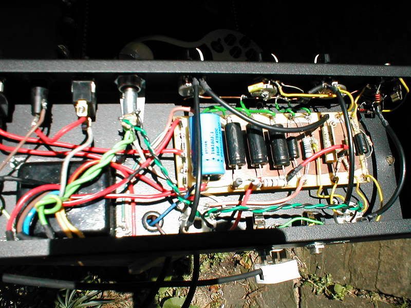
    Since the transformer orientation seems OK (You've done it before, I've seen it before...no problems reported) I'm suspecting the filament supply or filter grounding scheme. How are your power filters grounded???

    Chuck
    Last edited by Chuck H; 09-29-2007, 01:12 AM. Reason: typo
    "Take two placebos, works twice as well." Enzo

    "Now get off my lawn with your silicooties and boom-chucka speakers and computers masquerading as amplifiers" Justin Thomas

    "If you're not interested in opinions and the experience of others, why even start a thread?
    You can't just expect consent." Helmholtz

    Comment


    • #17
      Hi there Chuck,

      I have two paralled 16ufs (lhs on board), the left one grounded at the bttm rhs PT bolt.. then another 16uf grounded independently to the same PT bolt.. and a 3rd 16uf (preamp iirc, rhs filter cap).

      The only difference on schemos is my 1st paralled '32uf' pair (tied - ends obviously) not having the PT centretap as a gnd; instead I have this ct independently to the same PT bolt: so 3 whatnots only gnd at this PT bolt.

      Thanks Captain

      Comment


      • #18
        Originally posted by The Captain View Post
        Chuck the chassis design is based very similarly to the last (yellow one) example from this very good site- http://www.diycustomamps.com/princeton.htm

        I'm fairly sure, albeit an educated guess, that even if I shifted A from B on top of the chassis the hum would still persist.. oh and no change to hum when just preamp tube pulled out too.

        Thanks for thoughts so far, Capt.
        Steve M. is a friend of mine and many years ago, as a novice builder, he use to come over to my shop all the time for a few parts and some pointers.
        I think you could email him too and ask what kind of hum noise he has with this project... I wouldn't be surprised to find out I've seen it or maybe even worked on it at some time!
        Bruce

        Mission Amps
        Denver, CO. 80022
        www.missionamps.com
        303-955-2412

        Comment


        • #19
          Originally posted by The Captain View Post
          Chuck the chassis design is based very similarly to the last (yellow one) example from this very good site- http://www.diycustomamps.com/princeton.htm
          dunno if this is what you followed, but from looking at the "5F2-A Tweed Princeton Wiring" pdf file, the grounding scheme doesn't look the most ideal. I would for example, move the tone cap and vol. pot ground to the right to the input jack (super low level current returns, so group together). Also, if that isn't an isolated jack that wouldn't seem good. Also the preamp filter and power tube cathode R grounds, and the spk. out doesn't say if you are to use an isolated jack or not.

          Comment


          • #20
            I had similar reservations in regard to the power tube gnd being linked to the rhs preamp/ pot stuff (although Steve does mention his amps like this to be dead quiet). It is though the basic general layout I used, butt Ive separated the preamp gnd stuff/ pots/ jacks/ preamp filter gnd (all to a pot buss bar)-- from the power filter cap gnds/ HV ct/ filament ct (to their own PT chassis bolt). This method Ive used for 2 builds and dead quiet they are too. This one's still humming like mad.

            Comment


            • #21
              is there a picture of the chassis that can be looked at to see how things are hooked up?

              Comment


              • #22
                Yes indeed.. 1st/ 2nd filter caps paralled (blue atom and next one) & next filter cap & HV ct are together to own PT bolt. All other gnds go to the pot bussbar extending/ linking the input jacks gnd lugs. The filament ct (100ohm pair) goes to the 25uf cap/ 470r (via pin 8/ pin 1 of a 6v6 unused pins). The 2 metal spkr jacks' grounded where they are (tried them to the '3' at the PT bolt without any change in hum).

                Comment


                • #23
                  might be a dumb suggestion, but would it help to remove that black finish at points where connections are tied to ground...or am I just not seeing that?

                  Comment


                  • #24
                    TD's right any ground points should have the paint scraped away so there is good contact with the chassis material.

                    Are you using both ungrounded terminals on the master pot? You should just be using the middle terminal. I'm not keen on the way the wire from the master goes over the heaters on the way to 6V6 pin 5, in fact, I'd consider mounting the master on the underside/back of the chassis and running the coupling cap from V1, pin 6 horizontally to shorten the path.

                    Not crazy about the routing of that red hi voltage wire feeding the preamp plates, it would be nice if this was under the board.

                    Comment


                    • #25
                      Originally posted by TD_Madden View Post
                      might be a dumb suggestion, but would it help to remove that black finish at points where connections are tied to ground...or am I just not seeing that?
                      Perfectly sensible Q.. the first thing I did with the blank chassis is test across it for continuity- none, so I knew I was in for lots of scraping- which Ive done at each jack, pot, grounding bolt, switches, etc.. literally hours of work so at each now there's an excellent connection to the chassis, and all components very tightly secured on.

                      Comment


                      • #26
                        Hi Mark, I know wiring it not optimal here and there, but I have the exact same awful hum with or without MV pot wired in (same as Steve's site, and as I wired in one to great effect in a Vjr 5w; here tho its not sounding great- but this is not part of my concern at the mo), and routing other wiring exactly as you've suggested for trials- exactly the same hum, not even slightly different.

                        Appreciate the thoughts of course, Capt.

                        Comment


                        • #27
                          the workmanship looks pretty good but the grounding looks kind of discombobulated. I think it should be redone. The power tube cathode R/bypass ground looks wrong, and there isn't enough detail to see where everything is going. I would resort and move the grounds off the chassis except at the input.

                          Comment


                          • #28
                            Thanks, but I stated exactly where the grounds are before the pic, there aren't so many of them & with the pic it must be clear..

                            They go either to one PT bolt, or the pot bussbar, bar the filament ct going to bypass cap/470r as per the layout.

                            Cheers Capt

                            Comment


                            • #29
                              well the details matter like where the B+ center tap is, and where from the ground line you are setting down to the chassis (i.e. how you connecting to the rest of the ground line). Maybe that portion is from Randall Aiken's article where he uses two points down on the chassis and the way he does it has a logic behind it. If that logic is not understood, then you could be putting a noisy part down through the chassis. I see bits and pieces of things but not one unified logical system. For example, couple of the grounds after the rectifier are to the bolt but the power tube cathode/bypass are towards the preamp (high current plus also a big signal through the bypass cap) which looks like it could be problematic. It really helps to see clearly where are things are connected now to be able to suggest a change.

                              Comment


                              • #30
                                Originally posted by The Captain View Post
                                Thanks, but I stated exactly where the grounds are before the pic, there aren't so many of them & with the pic it must be clear..

                                They go either to one PT bolt, or the pot bussbar, bar the filament ct going to bypass cap/470r as per the layout.

                                Cheers Capt
                                The only thing that should be grounded to a chassis bolt or PT bolt is the power cord's green earth ground wire.
                                Take the red/yellow high voltage secondary center tap wire off that chassis bolt and move it to the negative lead of the first main B+ filter cap.... same thing with the power tube's cathode resistor and it's bypass cap... and it wouldn't hurt to tie the grounded lead of the OT to the same place as the power tube cathode resistor is grounded.

                                And... describe how all that unnecessary shielded cable is grounded.

                                These amps are really simple and it is very unusual to have bad hum problems.
                                So after those mods, you still have a hum issue, it has to be lead dress or something else unrelated to grounds... well, unless you really don't have proper grounds due to that coating on the chassis.
                                Bruce

                                Mission Amps
                                Denver, CO. 80022
                                www.missionamps.com
                                303-955-2412

                                Comment

                                Working...
                                X