Announcement

Collapse
No announcement yet.

Crate KX-160 KX160 Noise Help

Collapse
X
 
  • Filter
  • Time
  • Show
Clear All
new posts

  • Crate KX-160 KX160 Noise Help

    Picked up a KX-160 keyboard amp. It was cutting in/out, evident when wiggling some of the input jacks. Re-flowed all the jacks and that appears to be fixed. Now I notice a different problem, difficult to describe but if I hold an A note on the synthesizer, there will be an occasional static/crackle in the speaker. Sometimes it is more noticeable than other times when it is there but subtle. I have heard similar type noise with bad ICs in the past on other amps.

    I have tried to identify if it is on the pre-amp or power amp output section. The amp has a "Pre-Master" Line In and Line Out. It also has a separate Line Out with a level control.

    I sent the "Pre-Master" Line Out signal to another system and did not notice the noise. I sent another amp signal to the "Pre-Master" Line In and did notice the noise. So I think the problem is on the power output board.

    I have yet to located a schematic for this model. Looking for suggestions on what to try next.

    Thank you
  • #2
    Have you ruled out the speaker?

    Comment


    • #3
      Well I just went back to it and I am not hearing any issues when playing into a different speaker box, so.... my issue may be in this amps speaker box which has 3 components; a 15" speaker, a tweeter, and a cross over network. The issue is intermittent, so could any 3 of those items be ruled out?

      Comment


      • #4
        Originally posted by misterc57 View Post
        Well I just went back to it and I am not hearing any issues when playing into a different speaker box, so.... my issue may be in this amps speaker box which has 3 components; a 15" speaker, a tweeter, and a cross over network. The issue is intermittent, so could any 3 of those items be ruled out?
        You can rule out the tweeter by disconnecting it.

        The woofer typically does not go through the crossover.
        (sans solder connections)
        It wouldn't hurt to at least give the crossover a good look see.
        Last edited by Jazz P Bass; 03-28-2016, 01:12 PM.

        Comment


        • #5
          Will check it out. Thanks!

          Comment


          • #6
            Pulled the three components. Everything looks ok except the bullet tweeter is open (no continuity). Any suggestions on replacing the tweeter? I could probably order a diaphragm somewhere but wondering if there are wiser options. Thank you

            Click image for larger version

Name:	fostex-025h27-3.JPG
Views:	1
Size:	24.5 KB
ID:	841468

            Click image for larger version

Name:	fostex-025h27-1.JPG
Views:	1
Size:	247.4 KB
ID:	841467

            Comment


            • #7
              That 1" Foster compression driver is about the most common one there is.

              Free shipping to USA:
              Foster Factory Style Replacement Speaker Diaphragm N30, 025, H025, N27, N28
              Education is what you're left with after you have forgotten what you have learned.

              Comment


              • #8
                Parts Express Diaphragm for Old Version 4"x10" Midrange Horn or Similar Heppner/Foster-type Drivers

                Same thing- cheaper.

                Also: If the diaphragm is open, I doubt it's causing your symptoms. I'd be more likely to believe the woofer voice coil is rubbing or the cone is ripped, or the glue is loose on the spider. Give that thing a good inspection.
                Last edited by The Dude; 03-28-2016, 11:21 PM.
                "I took a photo of my ohm meter... It didn't help." Enzo 8/20/22

                Comment


                • #9
                  I had the same thoughts about the woofer. I inspected it and everything looks good.

                  I have a question about the function of the crossover. The crossover has a + and - input which has a speaker cable connected to it, that cable has a phono plug at the
                  other end that connects to the amplifier. The crossover has 4 output wires, a black/red pair each for the woofer and tweeter.

                  I measure continuity from the phono plug (+ and -) to the woofer wire pair as expected.

                  When measuring to the tweeter wire pair I have no continuity from the positive tip of the phono plug to either the black or red wire feeding the tweeter.

                  When measuring continuity from the negative tip of the phono plug I have continuity on both the + and - wire
                  feeding the tweeter. Is this normal?

                  I can see that the woofer circuit on the crossover board bypasses the crossover and that the tweeter circuit is going through the
                  cap, resistor, coil.

                  Thank you

                  Comment


                  • #10
                    Without a crossover schematic, we're punting. Saying that, the tweeter, as you say, "is going through the cap, resistor, coil", so the cap will prevent you from reading the tweeter voice coil (if that's what you're asking). Often, as part of the high pass filter, there is a low pass to ground after the cap to further keep low frequencies from the tweeter. If that is the case, you may read some resistance to ground after the cap even with the tweeter unhooked. Again, without seeing an actual crossover schematic, I've no idea what's there.

                    On the woofer, besides a visual inspection, APPLYING EVEN PRESSURE to the cone, move it up and down and listen for any sort of rubbing sound. There may be something rubbing (coil, chunk of glue, etc.) that you can't visually see without cutting off the dust cap. Also, if you tap on the cone with your finger, you should hear a nice low thump and no mechanical sounds. It takes some experience to be able to tell what is a good sound and what is a bad sound, so if you are unsure, compare it to a known working speaker of the same size and you can get a rough idea of what the thump should sound like.
                    Last edited by The Dude; 03-29-2016, 11:05 PM.
                    "I took a photo of my ohm meter... It didn't help." Enzo 8/20/22

                    Comment


                    • #11
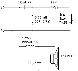
                      The schematic must be very similar to this one, but with the woofer connected straight through:
                      Juan Manuel Fahey

                      Comment


                      • #12
                        Originally posted by J M Fahey View Post
                        The schematic must be very similar to this one, but with the woofer connected straight through:
                        That's what I was thinking in my head, Juan. The post capacitor coil (.75mH) and the 12 ohm resistor to knock down the level would give you a resistance reading on the tweeter leads even with the tweeter unhooked. Measuring at the input terminals with the drivers disconnected would read open because of the 6uF crossover cap. I'm not sure if that is what misterc57 is talking about.
                        "I took a photo of my ohm meter... It didn't help." Enzo 8/20/22

                        Comment


                        • #13
                          I had similar questions on a Crate PE-15H PA speaker. Here is the thread - Crate Crossover Schematic For PE-15H

                          I addition to the Single Cap and Coil, Crate also used a Cap in parallel with a resistor, probably to act as a pad for the tweeter. Look for my hand drawing in that thread.
                          It's not just an amp, it's an adventure!

                          Comment


                          • #14
                            Sorry for not being clear. My question was a curiosity if the feeds to the tweeter were working correctly through the crossover.

                            With no speakers connected I measured no continuity from the positive input of the crossover to the positive output to the tweeter.

                            I did measure continuity from the negative input of the crossover to both the positive and negative output to the tweeter.

                            That seemed weird to me, bit in looking at the crossover schematic posted above, I believe my findings make sense now.

                            Also to confirm, my crossover appears to have a direct connection from its inputs to the outputs feeding the woofer, it does not appear to go through any cap or resistor.

                            I have attached the block diagram from the manual. Still have not found a schematic for this amp.

                            Thank you

                            Click image for larger version

Name:	xover.JPG
Views:	1
Size:	15.1 KB
ID:	841486
                            Last edited by misterc57; 03-30-2016, 02:45 PM.

                            Comment


                            • #15
                              Originally posted by misterc57 View Post
                              With no speakers connected I measured no continuity from the positive input of the crossover to the positive output to the tweeter.
                              This could be normal, as most crossovers have a capacitor in series with the tweeter, which will block the dc resistance reading.

                              If you don't have a schematic, can you post a photo or two of the crossover?

                              Comment

                              Working...
                              X