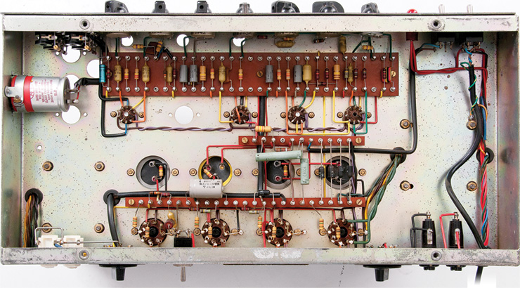
Announcement

Collapse
No announcement yet.

Randall rg100 Es ?

Collapse
X
 
  • Filter
  • Time
  • Show
Clear All
new posts

  • #16
    Here ya go
    Attached Files

    Comment


    • #17
      Well, there's 2 possibilities:

      1)TL604 is a good but obsolete signal switching IC, equivalent to an SS audio relay so perfect for channel switching, was VERY popular in the 80's and then faded away, Peavey, Fender and G&K used it a lot.
      Randall **might** have upgraded some last batch of RG100 using them, remember I told you original switching was crude by modern standards.

      Why isn't it in the schematic?
      Simple, the one floating around is an earlier version, nobody posted the last one.
      Which I know exists, because a problem in the original RG100 was that pulling the Sustain knob, which added 2 clipping diodes, killed volume/output a lot, was meant to be used in a recording studio, and in the latest models they had corrected that ... yet this last schematic was never seen.

      So you **might** have this latest version, with improved diode clipping and perhaps a TL604 switcher.
      I'd love to have your amp in my bench, pity we are 6000 miles away.

      2) somebody read that a TL604 was a good switcher, got on and plugged it in the first IC socket he found.
      Crazy?
      Yup ... but I have seen worse think 5U4 plugged in a 6L6 socket, etc. (hey!!, it also has 8 pins !!!!)

      Please post a couple pictures showing PCB end to end, the one you posted only covers a small area, we don't know how many 8 pin ICs you have: if 2, one might be reverb, the other switching; if just one: that TL604 has NO business in there.

      Does Reverb work?
      Do channels switch?
      Lots of guessing here because of insufficient data.
      Juan Manuel Fahey

      Comment


      • #18
        Ah I see. This one has 2 IC's. I see that the 1458 is working the reverb. I will try to get another pic later today.

        Comment


        • #19
          Ya that was a 100 ohm guy that got pretty hot. Has been fixed up and made new traces under the board.

          Comment


          • #20
            A better gut shot
            Attached Files

            Comment


            • #21
              Like J M Fahey says, I wouldn't trust a single schematic only since Randall often revised their amps. Not to mention, their current OEM source stuff is entirely different than their older products, which often carried same model names.

              In essence, that schematic you most often see circulating in the internet is applicable to those vintage "Red / Grey -stripe" -era Randall amplifiers, which already by then included many different variations of RG-80 and RG-100. In following years the designs often didn't drastically differ from the basic template but features like gain compensation of the sustain boost, treble boost, and impedance selector were implemented. Often cosmetic appearence of the amp changed too. Such changes were again featured in various versions of RG-80 and RG-100 series of amps.

              Do note that these products have been manufactured for about 40 years already! You can be sure they have been revised plenty of times.

              You can see ONE example of these circuit additions here:

              http://spaceryerson.com/pics/RG80-Schematic-1.jpg

              ...But unfortunately it does not provide much help as the scheme uses multiple-contact relay and is not relevant with product revisions possibly using TL604 instead. Overall, we can see that if audio signal path is concerned the circuit didn't change much. But it did change quite dramatically at that little part on which we happened to have special interest in (the channel switching and related) so it's no longer use as a refence. Unfortunately, most likely the schematic portraying the relay-based scheme is irrelevant with your amp revision as well....

              Did you try contacting Randall? If anything else fails, I advise you sketch the switching scheme yourself.

              Comment


              • #22
                Thanks for posting,
                Was always curious as to how they had solved the volume loss when adding clipping/"sustain" diodes, now I see it
                Juan Manuel Fahey

                Comment


                • #23
                  I called Randall yesterday but I had to leave a message. Wonder if they will call back?

                  Comment


                  • #24
                    Well, they might, they might not, you can politely call every day at different hours until you catch a Human.

                    The Company is probably as good or as bad as any other one out there, what I fear, let's say there's 50% possibility , they might simply answer: "we have no clue, that's a 35 years old product, we bought the company stock in 2002, got some 50 pounds of moth eaten yellowing old paper and blueprints, we'll check but no promises".

                    Fact is, with a couple very honorable exceptions such as Peavey, Marshall, Mesa Boogie, who else ? , none other is the real deal, definitely not the original one.
                    Vox is not Vox, Hiwatt is not Hiwatt, Ampeg went through a dozen owners even in the old days, etc.


                    Old defunct company heirs, think a grandson who nowadays owns a hotel or a couple fastfood premises or is an airline pilot or Banks who own whatever's left of a bankrupt company, including the`all important brand and right to use "contoured neck" or certain typical "looks" such as certain orange tolex, panel design, etc. and are NOT interested in Grandpa's business or solder fumes, will sell such rights to the highest bidder.

                    Which may very well be a group of investors who have no clue about anything except a profit and loss sheet, and often subcontract a Chinese company to do the actual work.

                    Problem is, you ask them about something made 30 years ago or more and they sincerely have no clue, not even the modern Chinese subcontractors, who had to start from a clean sheet of paper and maybe get "inspired" by schematics found on the Web.

                    Just onbe example of many:
                    kids adore (for good reasons) :


                    so they try to get their own:

                    (this one is Ron Wood's )

                    which if opened shows:


                    so they grab their savings and rush to the nearest GC , asking for a HIWATT .
                    The knowledgeable and polite "sales associate" stops playing with his smartphone and offers:

                    which as you see has the exact same Tolex, white piping, the famous Logo, similar knobs and panel lettering, and in a combo or cabinet, same grill cloth:

                    by the way, notice another famous impersonator in the same picture

                    Hey !!! it **LOOKS** the same, it must be the same !!!!!!

                    Only problem is that inside you'll find this instead (forget the rust, look at the engine driving it):


                    by the way, nothing wrong with it (I mean, the design and sound) ... just forget thinking "you are using the same as David Gilmour) and ............ would you ask the modern Chinese designer and builder about the real, British made 50 years old one?
                    Doubt he'll have the faintest idea ... at least beyond what he may ask at some Forum (such as MEF)

                    On the good side, yours is the "good" one, made in USA by the original makers, just an "unpublished" version ... improved by the way, it must have been one of the latest.
                    We'd love to have you trace and draw the schematic yourself (it takes patience, late at night so nobody bothers you, some coffee and good background music) at your own pace.

                    That said, politely insist with modern Randall Corporation Inc. (or whatever), you might get lucky.

                    At least in your case
                    Juan Manuel Fahey

                    Comment


                    • #25
                      Now that Was a fun response!

                      Comment


                      • #26
                        Could the foot switch be biasing the transistors?

                        Comment


                        • #27
                          Where did that come from I wonder?

                          Comment


                          • #28
                            Since that amp is *still* being called RG100ES I guess basic schematic is still the same , only *switching* was modded/changed improved,so we can guess how it was made.

                            1) original is by mechanical switching at the end of a long cable.
                            Problems:
                            a) you are connecting * internal* signal and sensitive points to a switch 15/20 feet away, through said length cable ... it should better be the *best* shielded cable available.
                            Potential to catch hum/buzz/radio is huge.
                            b) you are adding unwanted but unavoidable (cable) capacitance which will dull your sound.

                            2) relay (what Teemu showed): still mechanical but relay sits right on the board, worst case a few inches away, shielded by the chassis itself.
                            Only the DC relay coil connection travels to the far away footswitch, no need for shielded cable at all.
                            Potential problem is relay clicking and possible thump when coil is energized, but there's ways to attenuate that.
                            Slightly "expensive" (think $5/7 for a good relay) but used by many, think Fender HRD class and above, including over the top MB which can have as many as 13 of them.

                            3) analog switches/fets/transistors: small, light, inexpensive, easy to drive, what's not to like?
                            Have a couple limitations, usually signal voltage handling, so not usable all over the place in tube amps .
                            Another limitation is that closed analog switch resistance is not 0 ohms like on a relay contact but a not so low value, think 100 ohms class, so IF (just guessing) Randall Engineers just replaced the shorting to ground original switching with first: shorting to ground relay contacts , that would have muted unused channel as well as the old system, but if later replaced relay with TL604, again shorting either channel to ground ... those ~100 ohms remaining resistance would mean that a little bit of signal remained there ... and that's what I think is happening.

                            Can it be solved?
                            Short answer: not really, at least within the frame of a Forum question; of course Randall Designers can re-engineer the design in any way they seem fit and that's what they probably did.

                            I'd love to see the XXIst Century reedition of RG100 and see how are they switching today.
                            Juan Manuel Fahey

                            Comment


                            • #29
                              If you leave a message at any company, do not ask them to simply call you back. You should leave your name and phone number, mailing address and EMAIL address, then ask clearly and concisely what you want from them, such as latest revision of model XYZ123 schematic. Leave out anything about how long you had it and that you only just played it and it used to work and now it doesn;t and your friend had one etc. That way when they get the message, they don;t have to try to call you to find out what you want, they can just respond directly and send the thing email. remember, companies like that get a TON of calls and messages. Don;t do ANYTHING that makes it one bit harder to give the answer you need.

                              To them it is kinda like here, when someone starts a thread with the title: "A question". I don't even open those threads, frankly.
                              Education is what you're left with after you have forgotten what you have learned.

                              Comment


                              • #30
                                Here is a RG80-RG100 schematic from the 1997 series and you can see the relay being used for channel switching by this point.
                                Attached Files
                                When the going gets weird... The weird turn pro!

                                Comment

                                Working...
                                X