 Tweet
Tweet
I will post the most important mods for all the owners of these great and rare JTM60 amps. Works for JCM600 also.
The original mods come from a guy (Gunner) from metroamp, posted some years ago. I myself haven't done all of them and tweaked some to my liking.
I'll list the most important ones and the ones I'd done. I'll post 3 different schematics with mods. The third one is my edit of the original schematic with only the mods on my JTM. These will open the amp a lot, raise the bass and make the boost channel all tubeish, classic and vintage sounding.
Before I start, some tips on JTM's:
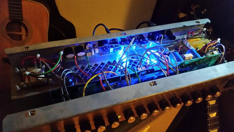
The amp is buildwise a bad design with power tubes directly underneath the electronics and big filter caps. So they suffer from overheating Problems. Do something about it. Some put an Alu plate between the power tubes and Chassis as a heat deflector and soak. I myself installed 3 mini PC-fans.
http://www.marshallforum.com/index.p...-03-jpg.35052/
Also, the original Bridge rectifier is a bit underrated at 6A. You can replace it with other with higher amperage Ratings (7A -10A). Install it a bit higher of the PCB so it dissipates heat better. The preamp tube sockets are cheap plastic and they can get wear from the heat. Replace with ceramic or even better the Micalex Sockel Noval Belton, Print VT9 - Tube-Town GmbH . Both heat resistant. Mine had too thick PCB terminal Pins so I drilled the original holes on a PCB a bit wider.
MODDING
READ BEFORE YOU DO THIS!!!
THE AMPS CONTAIN VOLTAGES THAT CAN KILL YOU. DO THIS AT YOUR OWN RISK!!!
-ALWAYS DRAIN THE VOLTAGES BEFORE WORKING ON AN AMP. ALWAYS CONTROL THE VOLTAGES WITH YOUR MULTIMETER
- NEVER PUT BOTH HANDS INSIDE THE AMP CHASIS.
- TO DRAIN THE CAPS VOLTAGE USE A 5 TO 10WATT RESSISTOR(10KOHM). CONNECT TWO CABLES WITH ALLIGATOR CLIPS TO RESISTOR. THAN PUT ONE END OF ALLIGATOR CABLE TO GROUND (CHASSIS) AND THE OTHER CABLE CLIP TO ONE OF THE BIG RESISTORS CLOSE TO BIG FILTER CAPS. LET IT DRAIN A MINUTE AND CONTROL THE VOLTAGE WITH YOUR MULTIMETER.
1) Use a Jumper cable in parallel FX loop's send/return. Easy. You get a subtle volume and fattnes control with the mix knob for parallel fx Loop at the front. I have it maxed always
2) cut the clipping diodes out of circuit. To do this just remove C105 capacitor. You will loose on distortion but this will increase the signal gain and the distortion comes only from tubes now. Very Vintage.
3) remove capacitor R104. Take C120 out and put it in R104's place. The tube will now distort in a wider frequency band.
4) put a 2,2uF cap parallel across the resistor R123. This gives you a bit distortion back.
5) Now, because of removal of diodes the signal increased a lot and we need to tame it down. Replace R126 for 220kOhm and R125 for 330kOhm. It works as a voltage divider and reduces signal a bit. The next one is tricky but important.
6) the Volume pot on boost channel VR6 works very sensitive now because of increased signal. If you turn it a bit you will saturate the stage very fast. So in order to take down the signal a bit more, you need to solder 2 resistors as voltage divider or even better a trimpot to be able too tune and balance the voltage more exactly, after V102B and before the VR6. You can either do this right before the cable CN108 or after CN5. Original mod was to use 2 100kOhm resistors (one to ground and than from the middle where the resistors connect to each other a path to VR6, as to pin 1 of CN108 or CN5, so you basicaly cut the voltage in half.
I used 22kOhm to ground and the first as 100kOhm, so I kinda cut the voltage more to about 1/4. It's basicaly "Vout=Vin x (22k/22k+100k)". Anyway there is very little space to do this. I soldered the resistors to the backside of PCB.
7) replace R116 on the V101A input grid to 22-33k. This rolls off some treble.
8) The next two are the more important mods for bass. Raise Cap C116 to 22nF. A mallory cap sounds good here.
9) raise the Cap C114 to 22uF. This opens the amp more. The original lower value reduces the bass a lot.
10) At stage V103. Replace R128 to 100kOhm. Replace the cathode resistor R131 to 820 ohm or 1kOhm.
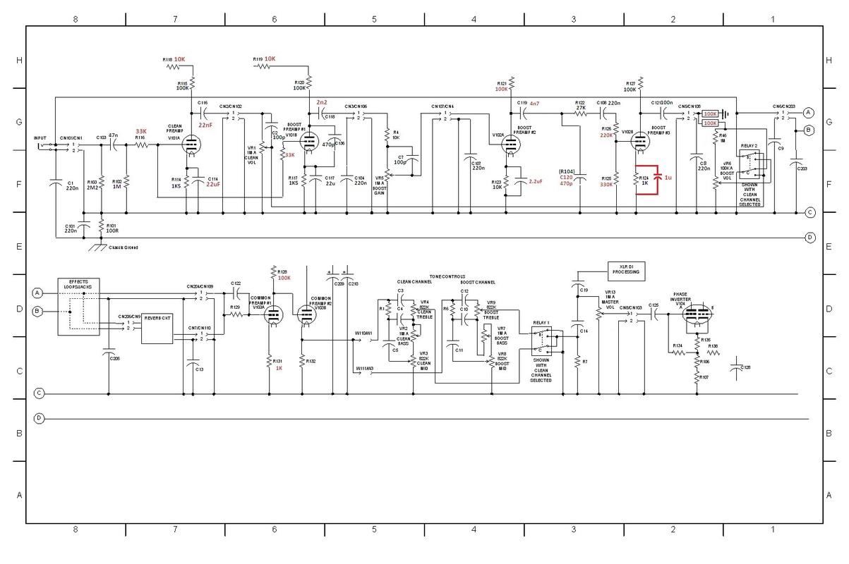
Now the mods I listed are the most important ones. On the pictures below you'll see some more mods in red. I've done only those mentioned above. There are also a few different schematics. It might be that stock values of resistors in your amp are not the same as in some JTM schematics.
http://www.marshallforum.com/index.p...-4-jpeg.35054/

http://www.marshallforum.com/index.p...-5-jpeg.35055/

http://www.marshallforum.com/index.p...-20-jpg.35056/
THIS THIRD ONE IS MY EDIT WITH ONLY THE MODS I DID TO MY JTM. Exeption is the second 100kOhm voltage divider to ground. I used 22kOhm instead.
Good luck. As I already mention the inside of the amp is a mess as you've seen yourself so take it easy and slow. Always document and make notes what you do. For example write everything down on a copy of the schematic as you work.
The original mods come from a guy (Gunner) from metroamp, posted some years ago. I myself haven't done all of them and tweaked some to my liking.
I'll list the most important ones and the ones I'd done. I'll post 3 different schematics with mods. The third one is my edit of the original schematic with only the mods on my JTM. These will open the amp a lot, raise the bass and make the boost channel all tubeish, classic and vintage sounding.
Before I start, some tips on JTM's:
The amp is buildwise a bad design with power tubes directly underneath the electronics and big filter caps. So they suffer from overheating Problems. Do something about it. Some put an Alu plate between the power tubes and Chassis as a heat deflector and soak. I myself installed 3 mini PC-fans.
http://www.marshallforum.com/index.p...-03-jpg.35052/
Also, the original Bridge rectifier is a bit underrated at 6A. You can replace it with other with higher amperage Ratings (7A -10A). Install it a bit higher of the PCB so it dissipates heat better. The preamp tube sockets are cheap plastic and they can get wear from the heat. Replace with ceramic or even better the Micalex Sockel Noval Belton, Print VT9 - Tube-Town GmbH . Both heat resistant. Mine had too thick PCB terminal Pins so I drilled the original holes on a PCB a bit wider.
MODDING
READ BEFORE YOU DO THIS!!!
THE AMPS CONTAIN VOLTAGES THAT CAN KILL YOU. DO THIS AT YOUR OWN RISK!!!
-ALWAYS DRAIN THE VOLTAGES BEFORE WORKING ON AN AMP. ALWAYS CONTROL THE VOLTAGES WITH YOUR MULTIMETER
- NEVER PUT BOTH HANDS INSIDE THE AMP CHASIS.
- TO DRAIN THE CAPS VOLTAGE USE A 5 TO 10WATT RESSISTOR(10KOHM). CONNECT TWO CABLES WITH ALLIGATOR CLIPS TO RESISTOR. THAN PUT ONE END OF ALLIGATOR CABLE TO GROUND (CHASSIS) AND THE OTHER CABLE CLIP TO ONE OF THE BIG RESISTORS CLOSE TO BIG FILTER CAPS. LET IT DRAIN A MINUTE AND CONTROL THE VOLTAGE WITH YOUR MULTIMETER.
1) Use a Jumper cable in parallel FX loop's send/return. Easy. You get a subtle volume and fattnes control with the mix knob for parallel fx Loop at the front. I have it maxed always
2) cut the clipping diodes out of circuit. To do this just remove C105 capacitor. You will loose on distortion but this will increase the signal gain and the distortion comes only from tubes now. Very Vintage.
3) remove capacitor R104. Take C120 out and put it in R104's place. The tube will now distort in a wider frequency band.
4) put a 2,2uF cap parallel across the resistor R123. This gives you a bit distortion back.
5) Now, because of removal of diodes the signal increased a lot and we need to tame it down. Replace R126 for 220kOhm and R125 for 330kOhm. It works as a voltage divider and reduces signal a bit. The next one is tricky but important.
6) the Volume pot on boost channel VR6 works very sensitive now because of increased signal. If you turn it a bit you will saturate the stage very fast. So in order to take down the signal a bit more, you need to solder 2 resistors as voltage divider or even better a trimpot to be able too tune and balance the voltage more exactly, after V102B and before the VR6. You can either do this right before the cable CN108 or after CN5. Original mod was to use 2 100kOhm resistors (one to ground and than from the middle where the resistors connect to each other a path to VR6, as to pin 1 of CN108 or CN5, so you basicaly cut the voltage in half.
I used 22kOhm to ground and the first as 100kOhm, so I kinda cut the voltage more to about 1/4. It's basicaly "Vout=Vin x (22k/22k+100k)". Anyway there is very little space to do this. I soldered the resistors to the backside of PCB.
7) replace R116 on the V101A input grid to 22-33k. This rolls off some treble.
8) The next two are the more important mods for bass. Raise Cap C116 to 22nF. A mallory cap sounds good here.
9) raise the Cap C114 to 22uF. This opens the amp more. The original lower value reduces the bass a lot.
10) At stage V103. Replace R128 to 100kOhm. Replace the cathode resistor R131 to 820 ohm or 1kOhm.
Now the mods I listed are the most important ones. On the pictures below you'll see some more mods in red. I've done only those mentioned above. There are also a few different schematics. It might be that stock values of resistors in your amp are not the same as in some JTM schematics.
http://www.marshallforum.com/index.p...-4-jpeg.35054/
http://www.marshallforum.com/index.p...-5-jpeg.35055/
http://www.marshallforum.com/index.p...-20-jpg.35056/
THIS THIRD ONE IS MY EDIT WITH ONLY THE MODS I DID TO MY JTM. Exeption is the second 100kOhm voltage divider to ground. I used 22kOhm instead.
Good luck. As I already mention the inside of the amp is a mess as you've seen yourself so take it easy and slow. Always document and make notes what you do. For example write everything down on a copy of the schematic as you work.

Comment