Announcement

Collapse
No announcement yet.

Bicentennial Firebird Pickup -- Magnet

Collapse
X
 
  • Filter
  • Time
  • Show
Clear All
new posts

  • Bicentennial Firebird Pickup -- Magnet

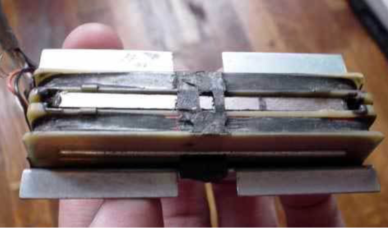
    Got a customer wanting a replica of one of these or as close as I can get. Have put one together and am testing it sans cover to avoid having to remove it with various changes, and it sounds really weak.

    The design is a sidewinder with a steel bar in each bobbin, sitting sideways with a ceramic bar in between. It's wound to 6.0k and I've got a Ceramic 5 bar in there -- dimensions 2.4" x .187" x .245" -- and it sounds like it's a foot away from the strings. The design seems to have a fatal flaw in it that makes this not surprising because the steel bars and the magnet itself are all a bit away from the top, thus away from the strings, more so than almost any pickup. Yet I suspect the real deal wasn't this weak.

    Another interesting thing I've read about it online is that "the bobbins are turned 90 degrees, as is the magnet". The magnet can't also be turned 90 degrees or you don't have N on one bobbin and S on the other. (I tried turning the mag 90 degrees and it was even weaker with an out-of-phase-ish tone to it.)

    What am I doing wrong here -- does it need to be Ceramic 8 or something?

  • #2
    I think you are referring to the B. L. patent.
    http://patentimages.storage.googleap...S3902394-1.png
    You may need to wire the start of one to the finish of the other.
    So check the wiring polarity.
    T
    "If Hitler invaded Hell, I would make at least a favourable reference of the Devil in the House of Commons." Winston Churchill
    Terry

    Comment


    • #3
      If that's the one, then your magnet should be as wide as the bobbin flanges (as shown in the diagram).
      In this invention, the pole pieces of the pickup coils
      are disposed so as to be located in a neutral part of the
      magnetic field of the permanent magnet so that such
      pole pieces are not loaded magnetically.
      The patent (US3902394) pretty much tells you how to build the pickup.
      Recommends 4250 turns of #42 per coil.

      This statement cracks me up.
      ...for reasons
      not known, this particular pickup construction works
      fantastically well.
      DON'T FEED THE TROLLS!

      Comment


      • #4
        I'm intrigued, and I'm gonna have to build one.
        To get the neutral null spot, since a bobbin flange is .514" you need a full 1/2 inch wide magnet bar.
        I would start with a 2.3"L x .5"W x .125" C8 magnet.
        Or for a thicker magnet like the patent drawing, carefully shorten a EMG C8 bass magnet, 2.6" x .5" x .200".
        http://www.mojotone.com/Pickups_x/Pi...gnet-2-60-Long

        Here is a write up on the pickups.
        It sounds like a sidewinder was only used in the bridge, and a regular firebird humbucker in the neck.
        Vintage Firebird Pickups | Bicentennial | Medallion

        Patent for the firebird sidewinder!
        http://www.google.com/patents/US3902394
        T
        Last edited by big_teee; 05-05-2016, 07:10 AM.
        "If Hitler invaded Hell, I would make at least a favourable reference of the Devil in the House of Commons." Winston Churchill
        Terry

        Comment


        • #5
          I've seen a picture of a real one disassembled. The magnet is not as wide as the flange. I tried a C5 that is and it does that slightly out of phase thing.

          Wiring polarity is fine. When I first had it together it was electrically out of phase so I just flipped one of the bobbins to put it back in and the signal is much stronger, does not sound out of phase anymore, but still on the weak side.

          Comment


          • #6
            Most regular sidewinders have the magnets in the bobbins, and a steel blade in between the bobbins.
            I make those all the time, and they work and sound great.
            You might try that design.
            Sidewinders are never as loud and as strong as humbuckers.
            GL,
            T
            Last edited by big_teee; 05-05-2016, 07:36 AM.
            "If Hitler invaded Hell, I would make at least a favourable reference of the Devil in the House of Commons." Winston Churchill
            Terry

            Comment


            • #7
              Originally posted by Zhangliqun View Post
              It's wound to 6.0k
              Originally posted by Zhangliqun View Post
              the signal is much stronger, does not sound out of phase anymore, but still on the weak side.
              Do we know that the originals weren't on the weak side? (Using the royal "we" here- I know that I don't know.)
              What does 6.0K translate to in turns per coil on your bobbins?
              Just guesstimating, if 5000 turns on a HB bobbin ~= 4.0K, then 4250 turns ~3.5K per coil = 7.0K total.
              DON'T FEED THE TROLLS!

              Comment


              • #8
                Originally posted by Zhangliqun View Post
                I've seen a picture of a real one disassembled. The magnet is not as wide as the flange.
                Maybe I'm too sleepy to know what I'm looking at, but in this photo from the article T posted, the magnet looks about flange width.

                DON'T FEED THE TROLLS!

                Comment


                • #9
                  Originally posted by Zhangliqun View Post
                  The magnet can't also be turned 90 degrees or you don't have N on one bobbin and S on the other. (I tried turning the mag 90 degrees and it was even weaker with an out-of-phase-ish tone to it.)

                  What am I doing wrong here -- does it need to be Ceramic 8 or something?
                  I am not a native english speaker, so I may have gotten something wrong reading your post but, from what I understand, you DON'T have to have N on one bobbin and S on the other. The magnet N (or S) should point to the strings and the bobbins should be placed in the middle of the magnets, where the polarity is "neutral". Steel is there unmagnetized just to increase inductance.
                  Last edited by Alberto; 05-05-2016, 03:11 PM.

                  Comment


                  • #10
                    Originally posted by Alberto View Post
                    I am not a native english speaker, so I may have gotten something wrong reading your post but, from what I understand, you DON'T have to have N on one bobbin and S on the other. The magnet N (or S) should point to the strings and the bobbins should be placed in the middle of the magnets, where the polarity is "neutral". Steel is there unmagnetized just to increase inductance.
                    Then how do you get hum-cancelling?

                    Comment


                    • #11
                      Alberto is correct, the magnet goes up and down, and the coils are sidewise.
                      If you will review everything I listed in post 4?
                      The links listed pretty well covers how it is made it shows a picture, and I listed the patent.
                      The patent explains how the magnet is oriented, and how the coils are wired.
                      The polarity and orientation of the magnet sets the phase.
                      The wiring of the two coils, is what cancels the hum.
                      T
                      Last edited by big_teee; 05-05-2016, 08:25 PM.
                      "If Hitler invaded Hell, I would make at least a favourable reference of the Devil in the House of Commons." Winston Churchill
                      Terry

                      Comment


                      • #12
                        Just to reiterate: The permanent magnetic field has nothing to do with cancelling hum.
                        Physical orientation in the same plane (or parallel planes) and reversal of end-to-end coil winding direction cancels hum.
                        (I hope I said that clearly enough. My native language is New Jersey patois.)
                        Last edited by rjb; 05-05-2016, 09:18 PM. Reason: Added parallel planes
                        DON'T FEED THE TROLLS!

                        Comment


                        • #13
                          Originally posted by big_teee View Post
                          Alberto is correct, the magnet goes up and down, and the coils are sidewise.
                          If you will review everything I listed in post 4?
                          It pretty well covers how it is made it shows a picture, and I listed the patent.
                          The patent explains how the magnet is oriented, and how the coils are wired.
                          The polarity and orientation of the magnet sets the phase.
                          The wiring of the two coils, is what cancels the hum.
                          T

                          Sounds right me. In a side winder, one would expect to have screws from the center up to the strings to guide the field up to magnetize the strings, and the varying field from the strings back down. Then there should be a piece of steel going through both coils (with magnets at the other ends of the coils) to turn this flux sideways so it goes into the coils pointing in opposite directions, and so the coils must be electrically out of phase for the signal to add. Meanwhile at least some of the hum from interfering fields gets guided through both coils in the same direction. Thus it cancels since the coils are electrically to of phase. I doubt that a sidewinder has very good hum rejection, but I guess it is better than nothing. (A hum field that points along the screws would not cancel.)

                          In any case, a ceramic magnet between the coils is absurd. Ceramic magnets have low permeability and do not guide the field well. And then no screws to go up to the strings? No wonder it sounds as though it is a foot away from the strings.

                          Comment


                          • #14
                            Mike, sidewinders actually work real well.
                            I prefer a magnet through each coil and a thin blade in the middle with a plastic cover.
                            Two EMG ceramics N/Blade/N, I can get 600-700 gauss from the blade, read at the top of the cover.
                            No screws required, works great for bass.
                            Hum cancellation is fine, the sidewinder benefits from additional shielding.
                            T
                            "If Hitler invaded Hell, I would make at least a favourable reference of the Devil in the House of Commons." Winston Churchill
                            Terry

                            Comment


                            • #15
                              Originally posted by Mike Sulzer View Post
                              In a side winder, one would expect to have screws from the center up to the strings
                              There are many variations of sidewinder designs. Presumably, some work better than others.
                              Seth Lover's 1959 humbucking pickup patent contained two sidewinder designs.
                              One used a row of magnetic pole pieces mounted in a soft iron bar, and two offset coils (three strings each) with iron cores. (Figs. 9, 10)
                              The other used a bar magnet down the center, again with two offset coils but with screws as the core material. (Figs 11, 12)
                              Both designs used offset coils "to reduce pickup or inductance between the two coils" and retaining plates to "project upwardly along the outer sides of the coils to form partial magnetic return paths between the ends of the permanent magnet".
                              The mechanical designs are pretty fussy/complicated, and I don't know if they were ever manufactured for sale.
                              Most commercially available sidewinder designs are less complex.
                              https://docs.google.com/viewer?url=p.../US2896491.pdf

                              Originally posted by Mike Sulzer View Post
                              In any case, a ceramic magnet between the coils is absurd. Ceramic magnets have low permeability and do not guide the field well.
                              I understand your reasoning.

                              Originally posted by Mike Sulzer View Post
                              And then no screws to go up to the strings? No wonder it sounds as though it is a foot away from the strings.
                              In terms of string magnetization, how is it worse than magnetic pole pieces or a magnetic rail pickup?
                              EDIT: OK, now I see. The magnet is too short to get near the strings.
                              Last edited by rjb; 05-06-2016, 02:22 AM. Reason: Added patent year
                              DON'T FEED THE TROLLS!

                              Comment

                              Working...
                              X