Announcement

Collapse
No announcement yet.

Jcm 800 build not giving any sound

Collapse
X
 
  • Filter
  • Time
  • Show
Clear All
new posts

  • Jcm 800 build not giving any sound

    Hi!

    I've build a jcm 800 2204 from the Ceriatone site
    http://www.ceriatone.com/images/layo...4Ceriatone.jpg
    But its not working.
    It's jsut dead silent. I already had a little help from another amp builder but he cant find the problem too.

    Here are some pics of the inside.
    http://smg.photobucket.com/albums/v472/Arathion/Jcm800/
    After these pics are made, i grounded the shielded wiring and switched the primary's of the OT (red and white wire's)

    I cant find the piece of paper where i noted down al the voltages so if you please could look at the pics first then ill get the voltages asap.
    I'd really liked if i can get the amp working.

    This is an pic of whats used ontop of the chassis

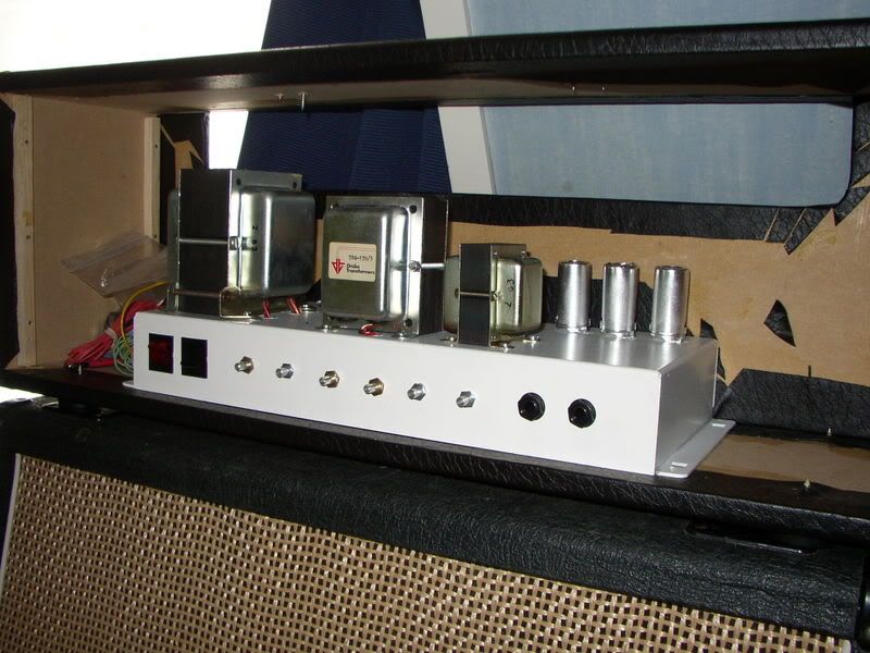
    Original Drake transformers!

    Ps if its in the wrong subforum please move..

  • #2
    Here are the measurements:

    All tubes have heating current between 6,3 and 6,4v AC

    V1:
    1: 319v
    2: 0v
    3: 3,52v
    6: 272v
    7: 0v
    8: 2,55


    V2:
    1: 198v
    2: 0
    3: 1,40v
    6: 394v
    7: 198v
    8: 0v

    V3:
    1: 262v
    2: 16v
    3: 53v
    6: 246
    7: 17v
    8: 53v

    V4:
    3: 488v
    4: 486v
    5: -44v (bias pot turnd full right)
    6: 489v

    V5
    3: 490v
    4: 488v
    5: -44v
    6: 489v

    B+ 490v

    Comment


    • #3
      V2 pin 8 should have roughly (don't panic if not identical) the same voltage as V2, pin 1.

      Is V2, 8 grounded perhaps?

      What current are you getting on the power tubes?

      Comment


      • #4
        Hmm, i have trace some bit back from pin 8 and i can tfind anywhere touching ground.

        The power tubes are noted as V4 and 5
        or do you mean current as in Amps? I dont know.. I dotn even know how to measure that.
        Please explain hot to measure that.

        Comment


        • #5
          Pin 8 of V2 carries yor preamp signal to the tone stack, if you have 0v here you will never get any sound out of the amp. Set your meter to ohms or continuity test and clip the black lead to the chassis, touch red lead to pin 8 (amp unplugged from wall AC for this). What do you get?

          V4 & V5 - negative voltage at pin 5 is not a very reliable indicator of the current being drwn by the power tubes, you really need to determine the plate current. Disconnect pin 8 of each power tube from ground, solder a 1ohm 2W resistor from each power tube pin 8 to ground. You can now read your plate current in mVdc with a voltmeter, by reading the voltage at pin 8.

          Comment


          • #6
            I don't have 1 ohm 2w resistors here at home, so i will have to go to the store tommorow to get some of them.

            I've checked resistance from pin 8 to ground and its giving 101kOhm. So that says it grounds behind the 100k resistor right?

            Comment


            • #7
              I might have accidentaly connected the ground that should go to the 500pf cap to the 100k resistor. But i cant see it very well, because it's under the board.

              Comment


              • #8
                I did grounded the 100k resistor

                Comment


                • #9
                  1ohm resistors - be sure to keep pins 1 & 8 connrected to each other.

                  Comment


                  • #10


                    I flowed all the solder joints round the 100k resistor. The ground came loose so now it runs over the board. I also experimented with other tubes. Nothing worked. I also used the dmm to check conductivity and if i put it into the pin socket and onto the lip on the other side i get conductivity.
                    I did the same test with het Ohmmeter. from pin 8 socket to ground this time. It measures 102kohm
                    It should all work normaly... But it doesnt..

                    (Havent got the 1 ohm resistors yet.)

                    Comment


                    • #11
                      Do you have voltage at V2 pin 8 now?

                      Comment


                      • #12
                        No....

                        Comment


                        • #13
                          As you have all wires connected under the board, pictures are not a lot of help, as we can't see which lead terminates where. But you should now have voltage at pin 8.

                          Check the V2 socket for shorts/damage/broken pin.

                          Comment


                          • #14
                            One side of V2 doesnt glow. but i cant detect anything bad one the socket.
                            And as i said it does connect good.

                            Comment


                            • #15
                              In the clearest shot I can see - V2, pin 7 appears to be damaged. Are you getting voltage here when you measure at the bottom part of the pin (that connects to the tube) rather than measuring at the resistor leg from V2, pin 1?

                              You said before that all tubes had heater voltage, I assume that this included V2, pin 9.

                              Comment

                              Working...
                              X