Announcement

Collapse
No announcement yet.

'67 Bassman Resurrection

Collapse
X
 
  • Filter
  • Time
  • Show
Clear All
new posts

  • #16
    Originally posted by g1 View Post
    ...In my experience with Fender amps from all decades, no particular type of cap (non-electrolytic) has stuck out as being more problematic than others.
    My personal experience is that the yellow Astron caps are the most prone to failure. Mostly they fail due to high DC leakage. I don't believe that it's due solely to age because I have seen the high failure rate for over 20 years and I hardly ever see a leakage failure with the blue molded caps that, by now, have proved to have a longer useful life than the yellow Astrons.
    Click image for larger version

Name:	1961 6G7-A Bandmaster_0004.JPG
Views:	1
Size:	416.7 KB
ID:	843422
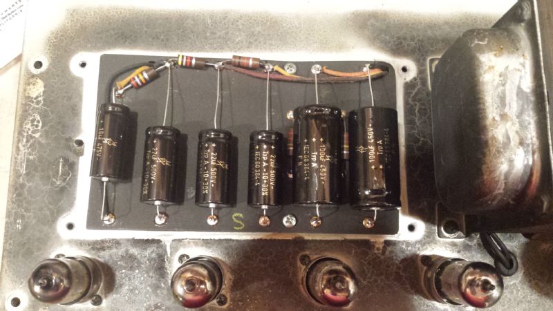
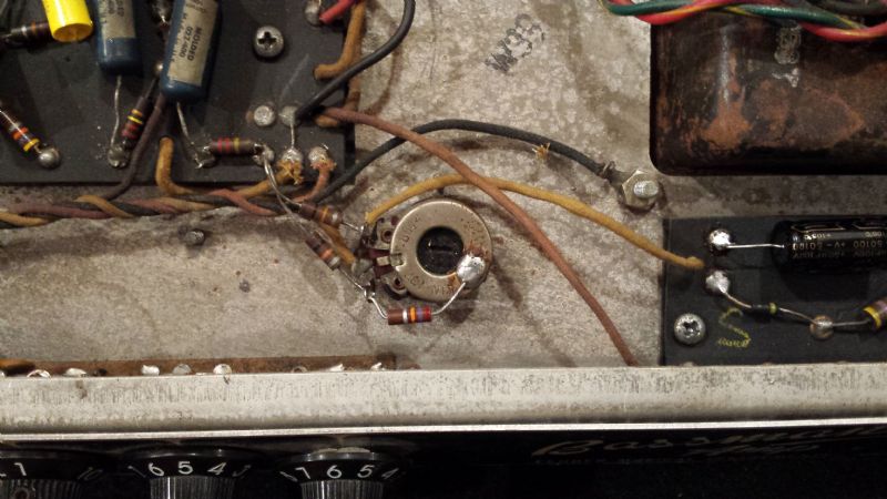
    The attached gut shot of a 1961 Bandmaster shows that the transition from yellow Astrons to Blue molded caps happened that year. The blues were then used throughout the blackface years and the first brown drop caps showed up around 1965 when it was common to see one or two browns in an amp.

    Cheers,
    Tom

    Edit: Fixed typo correcting 1691 to 1961. There are no existing 1691 Bandmasters. The last known unit was lost at sea when pirates attempted to smuggle it to England.
    Last edited by Tom Phillips; 08-27-2016, 11:38 PM. Reason: Fized typo.

    Comment


    • #17
      1691!?! That's VINTAGE!

      Comment


      • #18
        Wow, 1691 is even older than me!!
        Education is what you're left with after you have forgotten what you have learned.

        Comment


        • #19
          Ok. The amp is alive again. I replaced the Electrolytics first, then put a pair of matched Electro Harminix 6L6 tubes in and then powered up slowly. Everything seemed to function properly. I started checking voltages and found the bias voltages to be -54v high side(top lug in the photo), -45v wiper, and -43v low side. My voltages on the 6L6 tubes were equal at 399v. I played the amp and it seemed to be fine. It sounded very scooped in the mids, and the bridge pickup on my Strat was ice pick like. After about an hour of playing it on the bench, I decided to pull some of the coupling caps to see if they were leaky. The ones I checked, showed around .5 volts of leakage or less. I decided to go ahead with the switch to the Mallory 150's, but first I labeled the originals, in case we decided to go back. This was at 3:00 this afternoon and I had to leave before I could measure voltages. Fast forward to tonight. I go down to check voltages. Now I am getting 455v on the 6L6 tubes, -64v on the high side(top in the photo) of the balance pot, -53v on the wiper, and -53v on the low side. According to the schematic, the 6L6 tubes should be 425v, and the wiper should be -45v, + or - 20%. Am I correct in thinking that in order for this amp to biased/balanced correctly, that both voltages off of the high and low side should be equal, or close to it? There is not enough adjustment in the balance pot to correct it. If you reference the following picture, there is a 27k resistor to ground on the pot. In the schematic, it calls for a 15k. It appears that someone added the 27k resistor at some point in time as the solder and condition of the resistor does not match the rest of the factory work. Is this much difference in the negative voltages correct? If not, what could be the issue? Where did the extra voltage come from?


          http://www.thevintagesound.com/ffg/s...b165_schem.gif

          Comment


          • #20
            The bias balance isn't about making sure each tube sees the same negative voltage. It's about making each tube draw the same amount of current. The idea being, the resistors set the negative voltage from the bias supply, which goes straight to one tube. Then, the balance (in theory) is used to set one tube to draw the same current as the other by adjusting the negative voltage to Tue other tube. So basically, one tube is permanently fixed at some negative voltage, and the balance is used to adjust the other tube to match the fixed tube.

            There is a schematic around on the web that shows the best of BOTH: adding a true bias adjust to the balance already installed, so you can use mismatched tubes, too! I put it in all my Bassmans, since I scavenge for used tubes alot. If you give me some time, I can take some pictures and maybe draw a schematic.

            Warning: this mod will involve drilling a hole, unless you use a mini-pot or something. I just prefer to use a screwdriver, so I use a full-sized bias pot.

            Justin
            "Wow it's red! That doesn't look like the standard Marshall red. It's more like hooker lipstick/clown nose/poodle pecker red." - Chuck H. -
            "Of course that means playing **LOUD** , best but useless solution to modern sissy snowflake players." - J.M. Fahey -
            "All I ever managed to do with that amp was... kill small rodents within a 50 yard radius of my practice building." - Tone Meister -

            Comment


            • #21
              Originally posted by '66Cuda View Post
              Is this much difference in the negative voltages correct? If not, what could be the issue? Where did the extra voltage come from?

              Did you change the coupling caps between the PI and the power tube grids? If so, the ones you replaced were probably leaky which is why your power tube grids and plates have different voltages now. Leaky coupling caps from the PI would make the grids less negative. This would make the power tubes run hotter which in turn would pull down the plate voltage.
              The 27K resistor on the bias pot was changed to cool the bias on the power tubes. With modern line voltages, the increased B+ probably made the tubes run too hot, so someone adjusted the bias to compensate.
              Originally posted by Enzo
              I have a sign in my shop that says, "Never think up reasons not to check something."


              Comment


              • #22
                I bet it was a leaky cap. That never occurred to me. I did some research and found a method of checking the bias. I soldered a 1 ohm resistor between pin 8 and ground on the 6L6's. I then measured the voltage across those resistors. I came up with 28ma of current. 28ma*455v(pin 3) = 12.74 watts of static plate dissipation. My tube data sheet says 30 watts max, so that is around 42%. From what I could tell that was probably too low. I then removed the 27k resistor from the balance pot, and put in the original value of 15k. This jumped my current to 44ma. I figured that was probably too high. So I removed the 15k and put in a 22k. This got me to 36ma, and 16.38 watts(54%) of static dissipation. We played the amp for two hours tonight with no issues and it sounds great. Do you guys see anything that is off or incorrect?

                Comment

                Working...
                X