 Tweet
Tweet
Originally posted by 52 Bill
View Post
-
Yikes... my bad!The Blue Guitar
www.blueguitar.org
Some recordings:
https://soundcloud.com/sssteeve/sets...e-blue-guitar/
. -
Ouch!!!!I really do appreciate Juan's heads up on the wide influence of the Electra Distortion design although I did not see its resemblance to the Zendrive.
I think that reading my post you find different ideas written, depending on what we are talking about, context should make it clear.
Just in case it was misunderstood, my rant about Boutique Pedals (most of them and obviously there are exceptions) ends and then we are back to the OP question, which shows what looks more like an Electra than anything else, why do you think I said or implied that it�s the same or even comparable to the Zen or even *any* "op amp + diodes" distortion is beyond me.
As of the Zen schematic, I am not dissing it but fail to be *impressed* either.
There is a lot of terrain between those points and it falls somewhere in between.
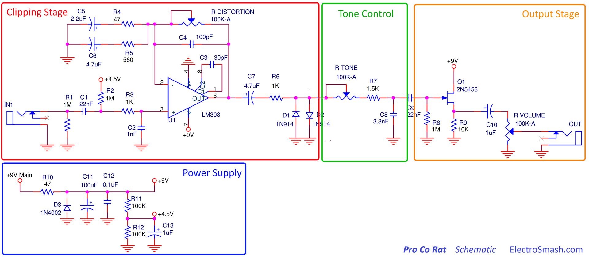
Here�s your schematic:

It can be split in two, the gain/clipping section and the tone control and output one.
* Gain/clipping:
built around IC1, with a 500k gain pot , clipping diodes in parallel, and a smaller value resistor to ground; a smaller than normal cap is in series so it cuts Bass and lowers sound muddying when overdriven.
wait a minute ... where did I see exactly that clipping amp configuration? :

looks the same to me, with some tweaks, some minor, some more important:
* instead of a fixed 4k7 resistor it has a 10k pot so value can vary around it.
* instead of a .047 cap it has a .1 one, so in sam setting it has slightly less bass (it might also have some extra muddyness, nothing is free).
* the one which seems to be the main contribution/originality: using **diode connected** MosFets instead of, cough!! , plain Si diodes, or Ge ones or Leds or Zeners or "amplified diodes" (� la Music Man and which I bet are closest).
ALL are similar, main point is all clip the same way: symmetrical (unless you stack different quantity or type one way or the other) and basically show a sinewave origin with flattened top.
There we have differences between Ge types which show quite rounded tops to almost square wave tops produced by Zeners.
Anything *between* those extremes is "no news" since all the range of waveforms has already been explored and in fact there are many pedals with switches to select one or the other at will.
Ok, I don�t have Zen clipping waveforms (although I might breadboard one, I have everything needed including the 2N7000 ..... somewhere) but to save time, I am including Voodoo Labs 2N7000 clipping waveforms:
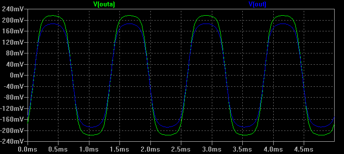
Haven�t I seen basically the same before? .... MANY times I might add:
enter (again) the mighty Tube Screamer:

before many point to the visible differences , such as almost vertical "walls" in the TS image vs the more sloping ones in the 2N7000 ones, it should be made clear that the TS was way more overdriven, that accounts for sinewave slopes being way more vertical (they quickly reach the clipping level) and viceversa, but I am quite certain that with similar overdrive (say , 20dB above the edge of clipping point) they�ll behave practically the same.
In a nutshell, I see nothing very original or impressive here, but a conventionsl diodes-in-the-feedback-loop distortion, with just anoother diode version ... it changes nothing radically.
I would have been way more impressed if they had used the 2N7000 as a 2N7000 , meaning as a gain stage.
It implies choosing a working point, biasing, etc. but would have been way closer to a tube clipping than to a plain diode.
As of the tone control and output buffer, I have again seen it somewhere, in the same configuration:
I am not dissing the Zen AT ALL, just fail to see the justification for all the hype, I bet even an unmodded TS can reach a VERY close sound
As of:as-is becomes somewhat optimistic, unless the full phrase is:recreate the sound of Robben Ford's playing of "Golden Slumbers" on the "Come Together Vol. 2" guitar tribute to the Beatles.
"recreate the sound of Robben Ford's playing of "Golden Slumbers" on the "Come Together Vol. 2" guitar tribute to the Beatles IF played by Robben Ford, using his guitar, plugged into his amp and recorded the same way"
There *may* be some complex digital pedal which emulates original distortion pedal, plus original amp and speakers plus original microphone type and position plus recording mixer settings , which is what we eventually hear; at least it�s physically possible, but to think that just inserting between a random guitar and speaker a simple 2 op amp pedal and expect that alone does all the magic (which is what many seem to believe) is, simply, optimistic.
Just a small rant:
the Zen schematic shows unsuitable linear pots, it will work way smoother if :
* gain: 500k Log
* voice: 10k anti-Log
* Tone: 50 k anti-log (works the expected way) or Log (as in Rat), works just as fine but counterintuitively counter-clockwise.
In any case we were talking the repackaged Joyo pedal, which by reseller�s own admission, was the same but with control range *reduced* , which in good English means the exact same sounds were available before.
If at least he had lowered or increased one cap or resistor value here, another there, or add new parts, or clip off and discard others, or modify clipping diodes type and quantity or other changes, so pedal now offered some thing NOT available on the original one, well, that might qualify better.
But as shown ........
By the way, I do not consider repackaging illegal or immoral, it�s being done all day long, every day, everywhere.
If customers think that a $200 pedal sounds way better than a $30 one, even after testingbthem side by side, then it�s their choice.
Applies everywhere and not just in Music.Juan Manuel FaheyComment
-
Juan,
I'll agree to disagree on the "repackaging." It may not be illegal, but I still think it's unethical. And even if one of you guys failed to patent an amp design and I stole it and produced it, I'd still try to give you some credit and maybe a token of (cash) gratitude. Just because laws don't plan for every single potentiality doesn't make it ethical...
If the same thing were applied to books and literature, there'd be a shitstorm. I think I'll go buy a few hundred copies of "Master Of Puppets" and paint over them, reprint the case sheets, a d put my name on them. That'll fly.
No, I'm not so idealistic to think that everyone would hold to my standards, but just because it's popularly done or not prohibited doesn't make it right. I guess I'm with the guys in the fifties, when they were pressured to do something the competition was already making. But, Ampeg didn't clone Fenders, and Gibson didn't clone Ampegs, and Gibson definitely didn't clone Fender guitars. So, yeah, I don't agree with just buying something cheap and rebranding it. And even if they DID "tweak" it, at least make your own damn circuit board!
Justin"Wow it's red! That doesn't look like the standard Marshall red. It's more like hooker lipstick/clown nose/poodle pecker red." - Chuck H. -
"Of course that means playing **LOUD** , best but useless solution to modern sissy snowflake players." - J.M. Fahey -
"All I ever managed to do with that amp was... kill small rodents within a 50 yard radius of my practice building." - Tone Meister -Comment
-
When I typed "I really do appreciate Juan's heads up on the wide influence of the Electra Distortion design although I did not see its resemblance to the Zendrive" late last night I was going to add a phrase like "but that could be because I don't understand FX pedal circuits very well at all" but got bogged down with the wording and left it out...
Whatever... no offense was intended.
Perhaps we can hear from someone besides me who has played a Zendrive or perhaps one of its clones- there is something really special in its sound and response that I don't find in other pedals, even though the electronic circuit itself might not look that special...
Steve AholaThe Blue Guitar
www.blueguitar.org
Some recordings:
https://soundcloud.com/sssteeve/sets...e-blue-guitar/
.Comment
-
Thanks
Just for kicks I�ll breadboard one and might even pack one inside a sandwich plastic case and lend it to some musician to try it.
Will not tell him "what it is" nor what it�s supposed to do, just "try this distortion pedal I�m experimenting with".
Not even need to design a special PCB, long ago I cloned an almost forgotten British PCB called "the blob" (I am a LONG TIME reader of Everyday Electronics, Practical Electronics, ETI and other hobby magazines from the British heyday) and it was a way too good idea not to be copied: they used to sell an experimenter�s pack made out of one of their own design protoboards, which was of curse reusable, plus 3 same size PCBs, with tracks which copied exactly the row and column array in the protoboard, and the trick is that they were *unperforated* , which is a long/annoying/boring part of making PCBs.
What�s the idea behind such a crazy design?
You build, tweak and perfection your design on the protoboard, then transfer it *exactly* to one of the matching PCBs .
Yes, exactly, even crossing paths (obviously at different heights .... as in the Protoboard) , adding track to track jumpers as needed, etc.
But .... but .... unperforated?
Yes, you built on the copper side up, slightly bent the parts lead tips (even in ICs or Leds) ,"everything became an SMT part", and the solder drop which joined a part leg with a copper track could in justice be called ..... " a BLOB"
And since all connections and parts are on the top side, said PCBs can easily be mounted against a panel, chassis floor or roof, Hammond case inside or even potentiometer backs with double sided tape or foam tape or a drop of adhesive.
Only compaint is that you waste more solder than usual and construction looks ugly ... but it�s functional and more stable than it looks ... certainly stronger than Proto since everything is soldered, after all.
And you need good light and eventually glasses to avoid shorting track to track ... not worse though than conventional Veroboard (which was its main competition).
You could buy 3 board refills for peanuts.
I made a silkscreen with that very simple design and turn all PCB scrap into "blobs" which are just etched, washed and left as backups, I don�t even remove silkscreen ink so it protects copper from oxidation, I wipe it before use with a rag and paint thinner or nail enamel cleaner.
This is a modern version, the wonderful Adafruit.
Of course, perforated and beautifully made
It should be WAY more popular than it is, but inexplicably they focus on the Robotics guys and not many outside them know or use them ... which is a pity.
The actual breadboard:
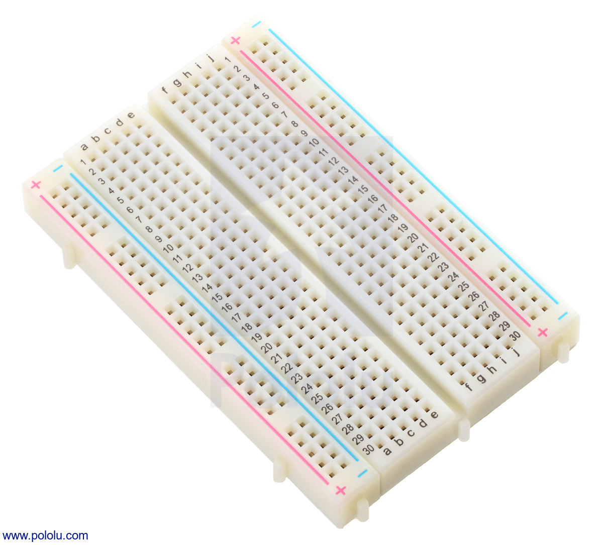
then you literally transfer prototype into "Veroboards" (there�s Full/half/quarter size and even flexible ones):


there�s even a perfect fit Altoids can PCB:
 Juan Manuel Fahey
Comment
-
I had an old Muff Fuzz in the small in-line chassis you plugged directly into the guitar's output jack. It also had the flying cobweb layout like the LPB-2 shown.
There are two interconnected complaints about many contemporary "boo-teek" pedals: 1) Their construction seems amateur, 2) the content and build quality doesn't seem to warrant the asking price.
To this I say that builders often work backward from their overhead costs to their asking price. If I have to pay rent and health/car insurance and I don't expect to make and sell more than 20 pedals in a month, then I'm likely going to tailor the asking price to what comes close to meeting my own personal costs. That doesn't mean it is warranted or isn't an example of what-the-hell-were-you-thinking-quitting-your-job hubris; it's just the mental math the person did.
In fairness, many highly prized vintage pedals were not exactly paragons of mil-spec quality. Not just the flying cobweb EHX pedals noted, but MXR turned out some pretty darn solder-intensive items. Jeez, I'd need a mile of solder-wick to clean the solder off my MXR M-113 Digital Delay. Just blobs and globs of the stuff. You wouldn't think it a "professional product" to look inside.
But with so much going the way of surface-mount wave soldering, teaching through-hole build quality is beginning to make as much sense as teaching students how to keep their typewriter ribbons properly inked.Comment
-
True, specially in commercial equipment, but booteequers still do things the old way, partly because of Mojo, partly ( mainly?) because that�s what building pedals on the kitchen table, home making PCBs, etc., through hole parts and similar Technology allows, so at least *they* should be skilled in hand soldering, hand mounting, manual wire layout, etc.Originally posted by Mark Hammer View Post
So if they still type on their old Underwoods, for any reason, at least they should keep their ribbons inked
The first example shown used tried and true eyelet-on-bare-board system; FWIW I still use the same (with my original 1969 eyelet press ) for simple stuff, such as adding a simple crossover and car lamp protection to a speaker cabinet, a simple (4 diodes and 2 caps) PSU, etc.
As fast and quite stronger than spiderweb construction
The system falls apart, though, when the first DIP package appears Juan Manuel Fahey
Comment
-
They look to be diode connected but I don't think they can work that way. There's a diode(s) connected in series preventing conduction in the normal direction (Drain to Source). The conduction path must be through the reverse Drain/Source body diode. That's the magic diodeOriginally posted by J M Fahey View Post
Comment
Comment