Announcement

Collapse
No announcement yet.

Sticking a BF Princeton and a 5E3 in a Champ Chassis. Sort of.

Collapse
X
 
  • Filter
  • Time
  • Show
Clear All
new posts

  • Sticking a BF Princeton and a 5E3 in a Champ Chassis. Sort of.

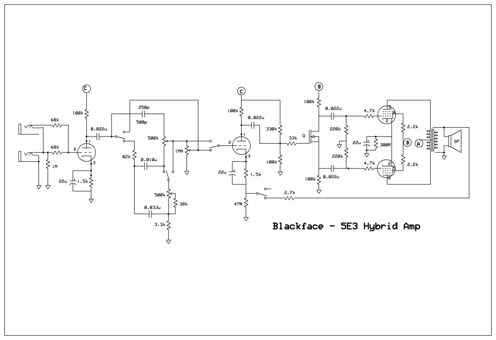
    Hey there ain't much room so you got to compromise. I never finished my MOSFET PI 12AQ5 amp, decided to go with the two triodes as gain stages and using my blackface-tweed tone control circuit. Then I thought, could I do a BF with a 5E3 volum-tone controls with a four pole switch? It was tough figuring out how to flip the controls around only using three pots. Then I thought dual pots but still a mess. Then I attacked it starting at the bass control to simulate the normal channel and it sort of fell into place. That is if it actually simulates what goes on in a 5E3. The 250p/500p cap, I am unsure of the value to go with. Will have to try real parts. What do you think? Crazy?


  • #2
    Image is not showing properly. It says "please update your account to enable 3rd party hosting".

    Comment


    • #3
      Yeah that sucks. No more free photobucket picture hosting. Just opened up an imgur account. Let's try this.


      Well definitely big enough.

      Comment


      • #4
        Are all those 2-pole switches switching/linked together or are they separately activated?

        Have you used that FET phase splitter before?
        ...and the Devil said: "...yes, but it's a DRY heat!"

        Comment


        • #5
          Four pole two position switch. Some of them do have an off middle position though. Not useful in this circuit though.

          Comment


          • #6
            An optional topology would be to use a FET (e.g. LND150) as the first stage and use a tube stage for the splitter.

            Comment


            • #7
              Regarding the tone controls - you could use dual (stereo) pots and have two parallell tone circuits. You could then use a simple DPDT to switch between the two circuits. These two circuits would be independent,so you could easily modify one without affecting the other.

              Comment


              • #8
                Originally posted by d95err View Post
                An optional topology would be to use a FET (e.g. LND150) as the first stage and use a tube stage for the splitter.
                I originally planed on using some FET's in the first stage running on the 12V dc supply I am using for the heaters. I am using the MOSFET in the splitter position as using a tube in this position does little for the harmonic content of the amp.

                Originally posted by d95err View Post
                Regarding the tone controls - you could use dual (stereo) pots and have two parallell tone circuits. You could then use a simple DPDT to switch between the two circuits. These two circuits would be independent,so you could easily modify one without affecting the other.
                I was going to put a circuit in that changes from BF tone stack to a Tweed volume and tone control but I was feeling up to a challenge and wanted to see if I could arrange the parts to get a 5E3 effect. I have a circuit drawn up with a DPDT switch going from a 5E3 circuit to a 5F6, not biased against using the switch.

                Comment


                • #9
                  Originally posted by printer2 View Post
                  I originally planed on using some FET's in the first stage running on the 12V dc supply I am using for the heaters. I am using the MOSFET in the splitter position as using a tube in this position does little for the harmonic content of the amp.


                  I was going to put a circuit in that changes from BF tone stack to a Tweed volume and tone control but I was feeling up to a challenge and wanted to see if I could arrange the parts to get a 5E3 effect. I have a circuit drawn up with a DPDT switch going from a 5E3 circuit to a 5F6, not biased against using the switch.
                  If you use a FET with a 12 volt supply you will have no clean signal unless you use very low gain, and then you have to make up that gain some other way.

                  The splitter should be the next stage after the output stage to over load as you increase the volume since the two outputs reduce the swing available to either one. Are you saying that want that to happen? The overload characteristics of that kind of one device splitter are generally considered to be not too good, although I think a FET might be better than a triode in this case. If you do not like the way that FET overloads, you could use two in the usual long tail "differential pair", adding source resistors to keep the gain down so that there would be no overloading of that stage. Or add a master volume in front of it. In this case the feedback would have to return to the right hand FET gate, not all the way back to the triode.

                  Comment


                  • #10
                    Originally posted by Mike Sulzer View Post
                    If you use a FET with a 12 volt supply you will have no clean signal unless you use very low gain, and then you have to make up that gain some other way.

                    The splitter should be the next stage after the output stage to over load as you increase the volume since the two outputs reduce the swing available to either one. Are you saying that want that to happen? The overload characteristics of that kind of one device splitter are generally considered to be not too good, although I think a FET might be better than a triode in this case. If you do not like the way that FET overloads, you could use two in the usual long tail "differential pair", adding source resistors to keep the gain down so that there would be no overloading of that stage. Or add a master volume in front of it. In this case the feedback would have to return to the right hand FET gate, not all the way back to the triode.
                    Well I was going to use two stages of gain with 2N5458's, 24k on the drain and 8.2k on the source with the first stage bypassed. Can't recall exactly how much gain, I had it in my other computer before it blew up. But I am sure I had enough clean signal to overcome the next stage triode's bias of 1.5V. But I changed my mind on what I want from the amp and am going triode first stage.

                    I don't think overloading the PI stage will be too much of an issue. I have not looked at the amp in some time but say if the output stage is running 260V and the screens and PI even 210V that would give 70V swing if the MOSFET is biased at 1/3 supply (ignoring losses). And the lowly 6AQ5 only needs about -15V bias on the grid so it will probably passing nice square waves before the preceding stage runs out of juice. I think it's overload characteristics are just hitting the rails as long as the proceeding stage has enough swing.

                    I am not sure if you can just simply plop the IRF820 (Someone asked me about the device and I realized the schematic didn't have it listed, will be on the next one) into a long tailed pair but I could be wrong. Mind you I did want to keep the amp simple, well if you ignore the switching it is more or less. You could just use a Tweed volume and tone and have a fun but dumb three tube amp. But since I don't mind running a few wires back and forth to a switch I think it is worth it to give some added variety. Or someone could just do a tone stack with a lift switch. But I do like having the tone control there if needed. Thanks for replying, I was starting to think having a MOSFET in there was putting people off.

                    Comment


                    • #11
                      Originally posted by printer2 View Post
                      I am using the MOSFET in the splitter position as using a tube in this position does little for the harmonic content of the amp.
                      I haven't built one myself, but judging by discussions on the forum and the many common mods for the 5e3 PI stage (e.g. grid stopper, biasing), it seems it has a rather big effect on the tone and distortion of the amp. I assume the PI stage affects the tone quite a lot. I assume that the PI stage has lower headroom than the preceeding gain stage, causing it to clip when pushed.

                      Doesn't mean it will sound bad or even significantly different with a FET stage though.

                      Comment


                      • #12
                        Originally posted by printer2 View Post
                        Well I was going to use two stages of gain with 2N5458's, 24k on the drain and 8.2k on the source with the first stage bypassed. Can't recall exactly how much gain, I had it in my other computer before it blew up. But I am sure I had enough clean signal to overcome the next stage triode's bias of 1.5V. But I changed my mind on what I want from the amp and am going triode first stage.

                        I don't think overloading the PI stage will be too much of an issue. I have not looked at the amp in some time but say if the output stage is running 260V and the screens and PI even 210V that would give 70V swing if the MOSFET is biased at 1/3 supply (ignoring losses). And the lowly 6AQ5 only needs about -15V bias on the grid so it will probably passing nice square waves before the preceding stage runs out of juice. I think it's overload characteristics are just hitting the rails as long as the proceeding stage has enough swing.

                        I am not sure if you can just simply plop the IRF820 (Someone asked me about the device and I realized the schematic didn't have it listed, will be on the next one) into a long tailed pair but I could be wrong. Mind you I did want to keep the amp simple, well if you ignore the switching it is more or less. You could just use a Tweed volume and tone and have a fun but dumb three tube amp. But since I don't mind running a few wires back and forth to a switch I think it is worth it to give some added variety. Or someone could just do a tone stack with a lift switch. But I do like having the tone control there if needed. Thanks for replying, I was starting to think having a MOSFET in there was putting people off.
                        The issue is not whether it has enough output to drive the next stage; it is whether you can run your humbucker equipped guitar with its volume on 10 (as much as 1V p-to-p or more) and not overdrive the FET.

                        Certainly there is nothing inherently wrong with solid state stages, but you can get into trouble in some circumstances!

                        Comment


                        • #13
                          Originally posted by d95err View Post
                          I haven't built one myself, but judging by discussions on the forum and the many common mods for the 5e3 PI stage (e.g. grid stopper, biasing), it seems it has a rather big effect on the tone and distortion of the amp. I assume the PI stage affects the tone quite a lot. I assume that the PI stage has lower headroom than the preceeding gain stage, causing it to clip when pushed.

                          Doesn't mean it will sound bad or even significantly different with a FET stage though.
                          There is a difference from the standard Cathodyne stage in amps like the Princeton, 5E3 Deluxe, various Ampeg amps and this stage. There is no tube mucking up the stage with its bad habits. The imbalance between the plate and the cathode impedance. The need for a grid stopper to shield the preceding stage from the grid conducting. All efforts to get rid of the distortion caused by the tube. As far as the stage having lower headroom than the preceding stage, is that not a good thing?

                          Comment


                          • #14
                            Originally posted by Mike Sulzer View Post
                            The issue is not whether it has enough output to drive the next stage; it is whether you can run your humbucker equipped guitar with its volume on 10 (as much as 1V p-to-p or more) and not overdrive the FET.

                            Certainly there is nothing inherently wrong with solid state stages, but you can get into trouble in some circumstances!
                            If you have humbuckers on ten let's hope that all the stages are overdriven, starting with the output tubes and moving forward. I am sure with any circuit you can get into trouble with any device. I am not too concerned about the PI in this amp, the guys here lent a hand when I first sparked this thing up.

                            Comment


                            • #15
                              So rather than wire up the circuit I wanted to see if I could hear anything with the first stage with the volume arranged like a standard 5E3. I used the a 500k pot to act as a load on the volume output and ran through the various combinations of the two listening what kind of effect the different positions would have on the sound. In each case when I turned up the volume I could reduce the gain with the other pot and nothing changed in the tone. Either there is something else going on with the 5E3 with the two channels or my ears are not sensitive enough to catch it. I will say that adjusting the gain with the second pot so that I had to use my guitar's volume control to add or subtract volume did change the tone. And that makes sense with the pot and pickup interaction. So in the end I abandoned the 5E3 volume and tone and arranged them the 'right' way.

                              While I was at it I tried out a circuit I thought up with only a two pole switch to change from Blackface bass and treble controls to a Tweed tone control. I thought I had something when I first thought it up until I realized that the lower capacitor in the tone control can be bypassed if the bass control is effectively shorted. In operation the effect actually gave the tone control a different feel, so rather than a flaw it turns out to be a feature. The cap values worked fine with the 8" speaker that the amp is feeding, I will have to try it with a larger one. In Tweed it is easy enough to get the amp into distortion, in BF mode there is enough gain to get a modest amount of distortion. So for now I am pretty happy with the amp for now. I still would like to add some NFB on its own switch and want to see if I can get some more voltage on the amp by rearrange the transformer and using a voltage doubler. I updated the schematic values, I transferred values from an old schematic and I guess I did some changes when I built it.


                              I am going to have to see about the picture sizes yet.

                              Comment

                              Working...
                              X