 Tweet
Tweet
I certainly got somewhat of an education here. The diode was on V1 as I remember. Would it have worked fine if I would have just removed the diode/resistor and replaced it with a 1.5 K with a 25 mfd cap in parralel ?
-
-
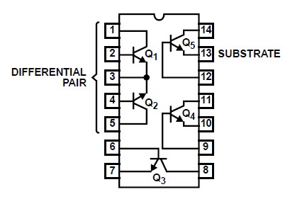
CA3046 chip is just a transistor array, basically five "discrete" transistors contained in a DIP package. Two have their emitters internally connected and I assume at least those transistors of the array are pretty well "matched" with each other.
Yes, the transistors are part of the channel switching circuitry: Most of the transistors are simply "shunting" various places of the signal path to ground in order to mute the channel not in use and prevent excessive crosstalk or channel bleedthrough. One transistor in the array simply performs inversion of the "logic signal" so that some transistors are saturated (and muting) while others are simultanously driven to cutoff state (and not muting). If you re-draw the circuit and replace the "black box with terminals" with discrete transistors (contained within the array) you will see that it's actually a super simple circuit for the job.
What's more interesting than the transistor array chip itself is the fact that those shunting BJT's seem to saturate (and clip the signal) with high-enough signal amplitude. I'm not sure if it ever happens under normal operating conditions though. That's another story though, and I'm quite sure Marshall designers didn't intentionally introduce that characteristic. Back then, FET's were scarcity.
---
As said, the cathode diode is providing a pseudo constant current load for the cathode. It basically clamps cathode voltage to diode forward voltage (about 500 mV) and therefore establishes a cathode voltage free of AC modulation. AC signals considered, there's not much difference to cathode bias circuit that bypasses a plain cathode resistor with high capacitance, except that - unlike a capacitor - the diode will provide level frequency response down to DC and is not subject to charging and DC level shifting.
That at least within certain input signal range...
Diode should theoretically provide constant current load, free of signal AC modulating the cathode voltage. In practice, diode's forward impedance changes with modulating AC current much more than capacitor's impedance - thus the diode scheme actually modulates the cathode voltage much more than a scheme where you have resistor bypassed with a capacitor. This is even greater concern with large signals swings because below the diode threshold voltage the cathode is simply loaded by 10K resistor SANS any bypass for AC!
I think the point of using the diode is - in theory - to provide more linear operation for the circuit. ...But this fails in practice, especially with great signal swings that exceed the operating range of the diode circuit. The diode-biased scheme seems to introduce more gain compression and THD overall. With high enough signals it also introduces more DC shifting than a resistive bias with AC bypass.
Now, I don't know whether Marshall designers intention was to keep the operation under the proper range, or exploit the effects of what happens when it doesn't...
Anyway, this biasing provides following operating conditions: Cathode DC bias voltage is about 500 mV and cathode's impedance for AC signals very low. With 430VDC B+ the plate voltage settles to about 80 VDC so if clipping happens it starts asymmetric and at the negative signal swing.
If we substitute the diode arrangement with 1K5 + big enough capacitor it provides following conditions: Cathode DC voltage increases to about 1.5VDC while impedance for AC signals still remains very low. Plate biases to about 110VDC.
Gain for AC signals is same for both schemes since diode is pretty much equivalent to capacitively bypassed resistor (except for level response that goes down to DC). In either case AC signal gain is identical and the clipping characteristics asymmetric.
What makes this even more interesting is that the stage provides some 60 volts (peak) of headroom for signal swing, which is subsequently clamped by shunt diode clipping arrangement that limits peak voltage swing to about 1.5V. So long before the stage ovedrives the diodes have clipped the signal to "square wave-ish" form.
IMO, this just looks like an arrangement to drive a solid-state diode clipper with a high headroom and high-gain stage. I'm not sure what Marshall gained with constant current bias vs. generic resistive cathode bias, given that gain ratios of these two circuits do not change, (a)symmetry of distortion does not drastically change, and that both circuit types have very high headroom to amplify cleanly vs. threshold of the following clipping limiter.
Maybe 1n4007 diodes were just cheaper than capacitors, perhaps the designer had seen some new circuit in an electronics magazine and wished to experiment with it...? Maybe it recovers faster from overload than RC bias circuit, where C gets charged...? Perhaps they wished to avoid "self-biasing" characteristic of RC cathode biasing where cathode voltage is a function of cathode current developing voltage drop across cathode resistance, instead of just being clamped to fixed level....?
I can understand the bias arrangement in the clean channel better: There's a (higher than usual) 150K plate load and simiarly a 10K resistor cathode bias - now SANS diode or any AC bypass! This actually biases cathode fairly high in DC voltage, and unbypassed cathode provides less AC signal gain and more potential for grid conduction induced clipping. "Off-center bias" at plate introduces asymmetry to that clipping. AND - most importantly - these clipping conditions are not "masked" by a subsequent diode clipper operating at much, much lower voltage threshold. So at least there is some potential to get some asymmetric, genuine tube gain stage clipping. In ovedrive channel the shunt diodes simply clip much earlier than that tube stage so that stage is left operating pretty much "transparently". So overall the diode bias doesn't make much sense to me there.
It would be interesting to hear motives for certain circuit design choices straight from the horse's mouth. So far we can just speculate and I'm out of any good idea what point diode-biasing serves there.Last edited by teemuk; 07-08-2017, 01:03 PM.Comment
-
Loudthud said .56v at 1ma. Where is .56 ohms coming from? 560mv/1ma = 560ohms.
Edit. Just saw this written below.
The diode slope resistance is (change in diode voltage)/(change in diode current) = (0.6V-0.56V)/(2mA-1mA) = 40 ohmsLast edited by lowell; 07-09-2017, 07:15 PM.Comment
-
In a nutshell placing a diode across the cathode, increases the gain of that stage which will give the amp more distortion. Myself I use a red LED on the first stage of my builds to give a little more bite to gain structure. The 10K is swamped out, removing it would have little audio effect. Of course you could substitute a capacitor across the 10 k and tweak the frequency response of that stage. A 10 Mf would give the gain but the bottom can get mushy, using a 0.05 Mf would give reduce the bottom kick and give emphasis about 800 hz and up, similar to what distortion pedals do before the gain stage (ie: tube screamer) The coolest thing on diodes, is the linear gain compared to cathode bypass capacitors, some modern tube hiFi amps mods using diodes on the input stage can impact the sound, in a interesting way.Comment
-
log curve.Comment
-
Since the voltage-current relationship is logarithmic, you can simply differentiate it and do a little rearranging to find the slope resistance. It works out to nominally 26 ohms at 1 mA for a silicon diode at room temperature, give or take a little bit to allow for doping variations, ohmic internal contact resistance, et cetera.Originally posted by Dave H View Post
For other currents, the nominal dynamic resistance is R (in ohms) = 0.026 volts / current in amps.
The "0.026" comes from the Shockley diode equation, and is the value of kT/q at room temperature, where T = absolute temp, k = Boltzmann's constant, q = electron charge.
-GnobuddyComment
Comment