 Tweet
Tweet
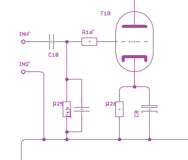
I'm building a Ceriatone Chupacabra. Here is its input layout. Input shield is tied back to ground at the jack.

Schematic (I think, hope it's correct):

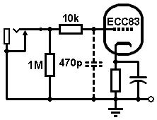
Now, here's the schematic for how it's typically arranged (at least according to ValveWizard, et al).
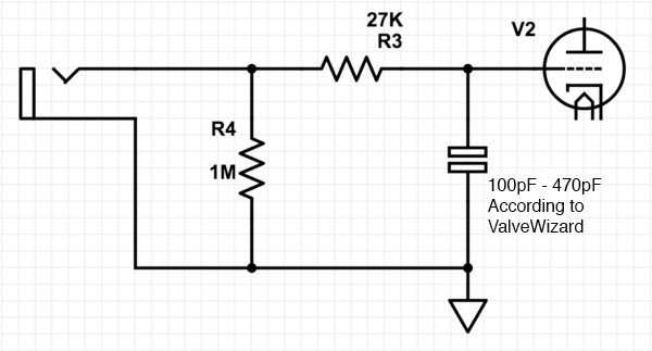
So can anybody help me understand what's happening here and why Ceriatone has:
1. Placed the 27K BEFORE the 1M, not AFTER (as Aiken explains—"The resistor should be placed after the grid-to-ground resistor (usually 1 Meg or so), to avoid attenuation and to keep the signal path short. If the resistor is connected in series with the input jack and before the 1 Meg grid resistor, there is a small loss of the input signal, although, in most cases the attenuation is not enough to be concerned with (0.94 times for a 68K grid stopper and a 1 Meg grid resistor), and in amplifiers with a high and low level input, the grid stoppers also serve as attenuators.)".
Either Ceriatone is intentionally attenuating the input signal or... ?
2. What the 0.1uF cap is doing in series, after the grid stopper. Is it there as a safety, to keep voltage off the guitar? When wired up as in schematic #2, ValveWizard explains that to reduce hiss/noise caused by the grid stopper, you can lower its value and then include a small cap from grid to ground to make up for the lowered resistance. Something on the order of 100pF - 470pF. But this is not what's happening in the way Ceriatone is doing it.
What are the pros/cons of each method?
Schematic (I think, hope it's correct):
Now, here's the schematic for how it's typically arranged (at least according to ValveWizard, et al).
So can anybody help me understand what's happening here and why Ceriatone has:
1. Placed the 27K BEFORE the 1M, not AFTER (as Aiken explains—"The resistor should be placed after the grid-to-ground resistor (usually 1 Meg or so), to avoid attenuation and to keep the signal path short. If the resistor is connected in series with the input jack and before the 1 Meg grid resistor, there is a small loss of the input signal, although, in most cases the attenuation is not enough to be concerned with (0.94 times for a 68K grid stopper and a 1 Meg grid resistor), and in amplifiers with a high and low level input, the grid stoppers also serve as attenuators.)".
Either Ceriatone is intentionally attenuating the input signal or... ?
2. What the 0.1uF cap is doing in series, after the grid stopper. Is it there as a safety, to keep voltage off the guitar? When wired up as in schematic #2, ValveWizard explains that to reduce hiss/noise caused by the grid stopper, you can lower its value and then include a small cap from grid to ground to make up for the lowered resistance. Something on the order of 100pF - 470pF. But this is not what's happening in the way Ceriatone is doing it.
What are the pros/cons of each method?


Comment