Announcement

Collapse
No announcement yet.

Need help connecting Power to spade connects on my Crate amp.

Collapse
X
 
  • Filter
  • Time
  • Show
Clear All
new posts

  • Need help connecting Power to spade connects on my Crate amp.

    Hello all.

    First post. Have lurked on and off for a couple years.
    First off I am not an amp tech. Nor can I read schematics.
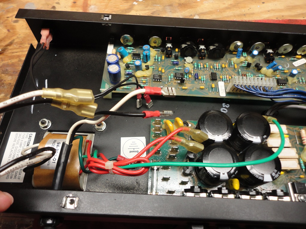
    I recently purchased a used Crate G130CXL.
    I decided to take it apart to clean some scratchy pots and jacks.
    I made a big mistake after discharging anything I thought might shock me.
    I unhooked the power supply from the power amp PCB.
    But I did not mark the wires or the board to put them back on their quick connect spades.

    All I need is perhaps someone to give me a heads up on which wires to put where.
    I hope I can post a couple pictures. Is that allowed?
    I looked at the schematics for a couple hours. . J9-J22. I only know where the green ground hooks up from the transformer. The rest might as well be in French.
    I would really appreciate the help.
    Click image for larger version

Name:	DSC00014 (2).JPG
Views:	1
Size:	276.4 KB
ID:	873149
    Click image for larger version

Name:	DSC00015 (2).JPG
Views:	1
Size:	252.2 KB
ID:	873150
    Click image for larger version

Name:	DSC00017.JPG
Views:	1
Size:	314.2 KB
ID:	873151


    Thanks.
    OM1972
    AKA Patrick.

  • #2
    Please post schematics.
    Originally posted by Enzo
    I have a sign in my shop that says, "Never think up reasons not to check something."


    Comment


    • #3
      Originally posted by g1 View Post
      Please post schematics.
      Ahh good idea. I think this will work. I think page 7 and 8 are the relevant ones.
      https://drive.google.com/file/d/0B_c...w?ddrp=1&hl=en

      Comment


      • #4
        G130CXL

        Your posted schematics are for GX130C and for G130CXL. I have not compared them, but would not assume they were the same, though they may be. MAke sure to use the right drawing for your amp. Geez, I hate doing this, ALWAYS make a map.

        Your transformer is simple, fortunately. the universal one has much more wiring. You have the white and black primary wires and the red secondary wires. The green is the center tap of the reds. All the push on males are along the end of the board except the one on the other side of the four filter caps. The green wire goes on that lone spade.

        Look on your schematic, the transformer connections are shown with connector numbers. That green CT one is to J9. The two red ones then must go on J10, J11. Look at the last layout, those two appear to be the somewhat isolated posts next to the pairs of big diodes. That solves the secondary. Now the primary. Your last layout shows the numbers fairly clearly, while the next to last layout shows the path of the copper traces on the board. Note how several of the posts are simply wired together, a place to connect several wires together.

        The white power cord wire goes to J19. The black to J12 by the fuse. The transformer primary white goes to J20. Transformer black then goes to J16. The two black wires from the power switch go to J13, J14.

        Aha, g1 beat me to it while I was typing.
        Education is what you're left with after you have forgotten what you have learned.

        Comment


        • #5
          Please ignore my previous (deleted), the board layout of schematics does not match your pictures. Update in progress.
          Last edited by g1; 12-14-2017, 04:15 AM.
          Originally posted by Enzo
          I have a sign in my shop that says, "Never think up reasons not to check something."


          Comment


          • #6


            1 (not shown, other side of big caps) green
            2 red (either one)
            3 black of AC cord
            4 black from switch (either)
            5 black from switch (either)
            6 black from transformer
            7 white (either)
            8 white (either)
            9 red (either)

            Click image for larger version

Name:	130wrg2.jpg
Views:	1
Size:	57.2 KB
ID:	847952
            Originally posted by Enzo
            I have a sign in my shop that says, "Never think up reasons not to check something."


            Comment


            • #7
              I downloaded the schematics you provided of the Crate amp, and have copied the first photo, showing the primary and secondary PCB terminals tht you forgot to document. And, cropped the schematic portion of the circuit, and will try to direct you with the wiring.

              Click image for larger version

Name:	Crate AC Mains PCB-1A copy.jpg
Views:	1
Size:	107.2 KB
ID:	847953 Click image for larger version

Name:	AC Pri-Sec Schematic-1 copy.jpg
Views:	1
Size:	39.0 KB
ID:	847954

              I've added wire colors to the schematic, so looking at your power cord wires, the Blk wire connects to J12, which should be the only connection to the left side of the Fuse. One of the BLK wires of the Power Switch connect to J13. The other BLK wire from the switch connects to J14. The BLK wire from the Pwr Xfmr Primary connects to J16. The WHT wire of the Power Cord connects to J19. The WHT wire from the Primary of the Pwr Xfmr connects to J20. Then, the RED wires of the Pwr Xfmr secondary connect to J10 & J11. The GRN wire is the centertap of the Secondary wire, and I've yet to find where terminal J9 would be. Is there a blade terminal in the middle of the four power supply caps? fi so, that's where the GRN wire plugs onto.

              I think the pair of terminals to the left of the Fuse are J17 & J18. No connections are made to those.
              Last edited by nevetslab; 12-14-2017, 04:38 AM.
              Logic is an organized way of going wrong with confidence

              Comment


              • #8
                Uh oh, is mine in error then? I assumed his board matched my schematic.
                Education is what you're left with after you have forgotten what you have learned.

                Comment


                • #9
                  Thanks for all the help guys. It worked for all of them.
                  Seems I have a bad part somewhere.
                  The amp works but the volume is very low on both channels when dimed.
                  It worked before but was switching speakers one fading then the other,back and forth when amp got warm.
                  A first cleaning seemed to improve it. But was still not quite there. So I did it again, made my no wire map blunder. (sorry guys)
                  If I hook a guitar up to the effects return on the front of the amp I get full power.
                  Maybe still dirty contacts in the jacks?
                  Or there is some fault in that ridiculous wire loom between the two boards?
                  Perhaps too much 2-26 still not totally dry somewhere causing a short?
                  Or just could be this amp has seen it's last days unless it gets a wholesale parts replacement.
                  No worries though. It is a $20 as-is special.
                  Again I appreciate getting some help and on the fly lessons on primary and secondary wires from a transformer.
                  I will hang around and ask more questions on this thread, or others, if I choose to poke around in this old beast some more.
                  Cheers.

                  Comment


                  • #10
                    If the amp even functions, your power transformer stuff is working...move on.

                    Reclean that insert jack.
                    Education is what you're left with after you have forgotten what you have learned.

                    Comment


                    • #11
                      If the amp even functions, your power transformer stuff is working...move on.

                      Reclean that insert jack.
                      Education is what you're left with after you have forgotten what you have learned.

                      Comment


                      • #12
                        Having found you're getting full signal thru the Effects Return jack, you have an amp that works, and it may just be contacts. On gear that hasn't been running for some time, sitting on a shelf , I'll exercise all the controls and switches (signal path switches). Rack the pots back and forth a bunch, one at a time. Push button switches...poke them in and out a bunch of times. Circuit board interconnects.....if they're not the same as the primary/secondary connector type we helped you restore (those are usually solid), other types....you can carefully un-plug/re-plug a few times (one connector at a time!), as this metal-to-metal insertion /removal action wipes the surface of the contacts, a cleaning action. With your guitar's cable, you could exercise the input jacks in the same way.

                        Now, It's also feasible that you have solder fractures on pot solder terminals, input jack solder terminals and other parts in the front end ahead of your Insert Send/Return jacks. That gets into the technical servicing act. With bright light and magnification, you can physically see them, or at least go for thorough inspection. Here's a photo of what you're looking for (solder fractures)

                        Click image for larger version

Name:	SVT-CL-Bias Pot Fractures-1.jpg
Views:	1
Size:	260.4 KB
ID:	847955 Click image for larger version

Name:	Pre Out-Pwr In Jack Solder Joints-2.jpg
Views:	2
Size:	203.6 KB
ID:	847956 Click image for larger version

Name:	SVT_Pro4_BridgeRect-1.jpg
Views:	4
Size:	68.4 KB
ID:	847958

                        See the radial void around the component leads in some of the terminals? Those are solder fractures. They become intermittent connections, and in some cases, can do harm, in other cases, just make the amp behave irrationally (or in the case of the 3rd photo, not work at all). The cure? De-solder and then re-solder. Those gremlins may be alive and kicking in your amp, and be the reason you were able to buy it for $20. Cure it, and you've learned a lot and got yourself a prize!

                        You've already been bold enough to go digging inside for clues.
                        Last edited by nevetslab; 12-14-2017, 06:02 PM.
                        Logic is an organized way of going wrong with confidence

                        Comment

                        Working...
                        X