 Tweet
Tweet
Originally posted by prschmitt
View Post
-
dude, I have the centertap here as well! If this is causing the problem, then the large value cap helping makes sense. Im going to look into this and change the reference. Thank for sharing thisIf I have a 50% chance of guessing the right answer, I guess wrong 80% of the time. -
This is very interesting. I think the voltage on the un-bypassed shared cathode resistor would swing about 15V at full output. The waveform of that voltage is ‘rectified’ and contains a lot of harmonics. The heater and the cathode of V1 are in close proximity and have capacitance between them, even if the heater-cathode insulation is strong.Originally posted by prschmitt View Post
We already know that heater-to-cathode leakage current on V1 can be a source of hum. The high harmonic content of the signal coming back from the power stage could result in a greater effect.
Knowing what we know about lead-dress, we would be very reluctant to bring a wire with 15V amplified and rectified signal in close proximity to the cathode of V1.Comment
-
I'm going with this as the problem. One of the reason i don't like EL84's, i've seen bad crossover distortion on many factory amps.Originally posted by frus View PostComment
-
This is impossible. There is no capacitor to charge. Its a direct coupled stage.Originally posted by mozz View PostIf I have a 50% chance of guessing the right answer, I guess wrong 80% of the time.Comment
-
Yeah, impossible then. Unless there is something wrong with that direct coupling
Mozz, that trick with the zeners actually works. You are clipping the part of the waveform that's not being amplified anyway. In amps with different power tubes, the bias voltage is higher, so the PI does the clipping for you at, say, double the bias voltage. Also, EL84 amps are most often cathode biased, so the bias shifts anywayComment
-
Still waiting on schematic, that why i said that. You have a non common setup so a schematic would help us all to see whats going on.
So what am i seeing on these terrible el84 waveforms? Grid blocking and not crossover distortion?Comment
-
Also interesting (I should probably try to recreate the issue for research sake) was, IIRC, that the oscillations were appearing on signal peaks only.Originally posted by Malcolm Irving View Post
No input, no oscillations.Comment
-
Sorry for the late reply. We've bee digging out from a bomb cyclone that hit us yesterday.Originally posted by mozz View Post
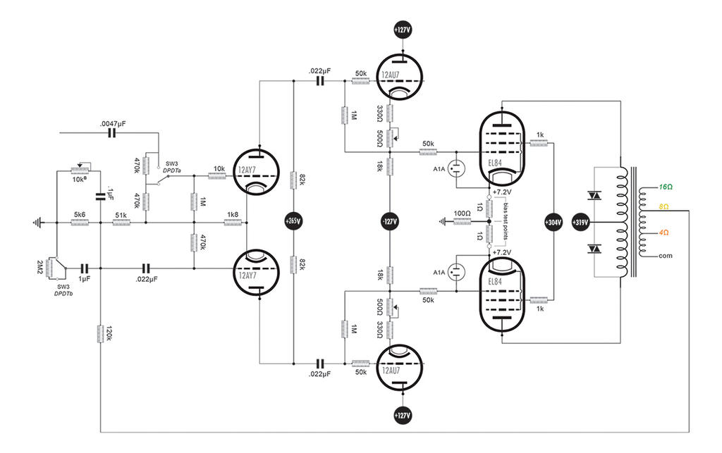
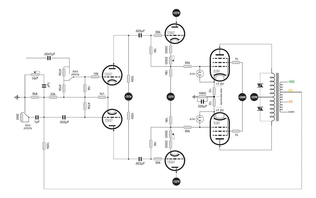
Here is are the schematics; the first showing the operating characteristics of the first 12AY7 Phase inverter, and the second showing the operating characteristics of a 12AX7 PI.
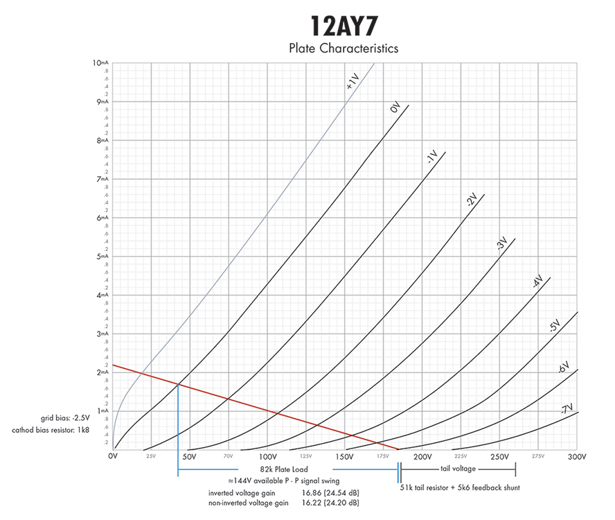
Nothing too exotic here. As you can see by the load lines, all things being equal, the 12AY7 provides a larger peak-to-peak output voltage swing with roughly a little over twice the input headroom. Or another way to look at it, it requires a little over twice the input voltage to drive it to it's full p-p output.
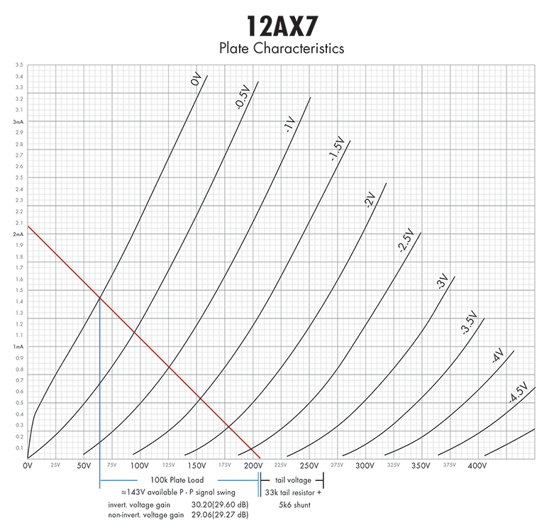
Since, I'm driving EL84's (which have arguably the highest input sensitivity of commonly used output tubes), I don't require a very large P-P output swing and wasn't necessarily looking for, or need lower sensitivity at the input of the PI. I was able to redesign the PI for a 12AX7 with about twice the voltage gain and the same peak-to-peak output voltage swing at the expense of better balance in the Long Tail Pair.
As for the Cathode followers driving the EL84s, they are being operated in their linear region and should function as a purely transparent stage. The the bias point of the CFs set the bias point of the EL84s, so they have a headroom of +40V positive voltage swing and over -100V negative voltage swing at the input. So, all other stages will clip WAY before they do.If I have a 50% chance of guessing the right answer, I guess wrong 80% of the time.Comment
-
prschmitt! You clever son of a bitch you nailed it! After checking the unbypassed output waveforms and cathode voltages at 440Hz and 1kHz, I removed the heater CT reference from the + side of the cathode resistor and left the resistor unbypassed. Slowly brought up the gain into clipping and pretty heavy overdrive with no trace of that transient "buzzy" distortion! At least preliminarily, things seem nice and stable. If you hadn't already run into this issue, I don't know how long it would have taken me identify that. The Heater CT wasn't anywhere NEAR my radar on this one. I appreciate you chiming in on this one.
I think this bears some further investigation. Unfortunately, the resolution on my Rigol is terrible and the manual controls are jumpy and garbage. It makes it difficult to zero in on, and clearly see any distortion artifacts on a waveform.Last edited by SoulFetish; 03-05-2018, 02:20 PM.If I have a 50% chance of guessing the right answer, I guess wrong 80% of the time.Comment
-
Yikes. So when do we not want to use the cathode voltage to elevate the heaters?Originally posted by Enzo
Comment
-
I'm pretty sure it's eliminated by using a bypass cap on the cathode. Whatever AC is riding on the cathode circuit is the culprit. A bypass cap gives the AC a low impedance path to 0V."Take two placebos, works twice as well." Enzo
"Now get off my lawn with your silicooties and boom-chucka speakers and computers masquerading as amplifiers" Justin Thomas
"If you're not interested in opinions and the experience of others, why even start a thread?
You can't just expect consent." HelmholtzComment
-
I'm ecstatic that I was able to help.
I was afraid that you'd solved the issue and I might have been barking up the wrong tree for your situation.
Referencing to the cathode is pretty much SOP.Comment
-
As long as the capacitance is large enough, I think your right Chuck. Had prschmitt not mentioned the heaters, I probably would have just left the cap in place as the fix.Originally posted by Chuck H View Post
Going forward, when choosing a location to elevate the heater supply, it is imperative that they do not tie it to the shared unbypassed cathode resistor. I personally, will never tie CT of the heater supply to this junction again.
 I don't even want to tell you guys what... how many times I thought I had this figured out. Trying to work backwards to what the hell changed to start causing it.
If I have a 50% chance of guessing the right answer, I guess wrong 80% of the time.
I don't even want to tell you guys what... how many times I thought I had this figured out. Trying to work backwards to what the hell changed to start causing it.
If I have a 50% chance of guessing the right answer, I guess wrong 80% of the time.Comment
Comment