Announcement

Collapse
No announcement yet.

Effects of cathode bypass capacitor on output stage overdrive characteristics

Collapse
X
 
  • Filter
  • Time
  • Show
Clear All
new posts

  • Effects of cathode bypass capacitor on output stage overdrive characteristics

    I was experimenting with change in the design of my phase inverter to drive more voltage gain into an El84 output stage. The output tubes are biased using an shared un-bypassed cathode resistor. I was running into a problem when the amp would transition into overdrive. I was getting awful buzzy distortion characteristics that almost sounded "super-imposed" on the normal clipping sound. It almost sounded like the speaker was causing small hardware to rattle in a tool box, if you know what I mean. After trying a number of common fixes, adjustments, and swapping out the speaker as a means of ruling it out as the cause, I was stumped.
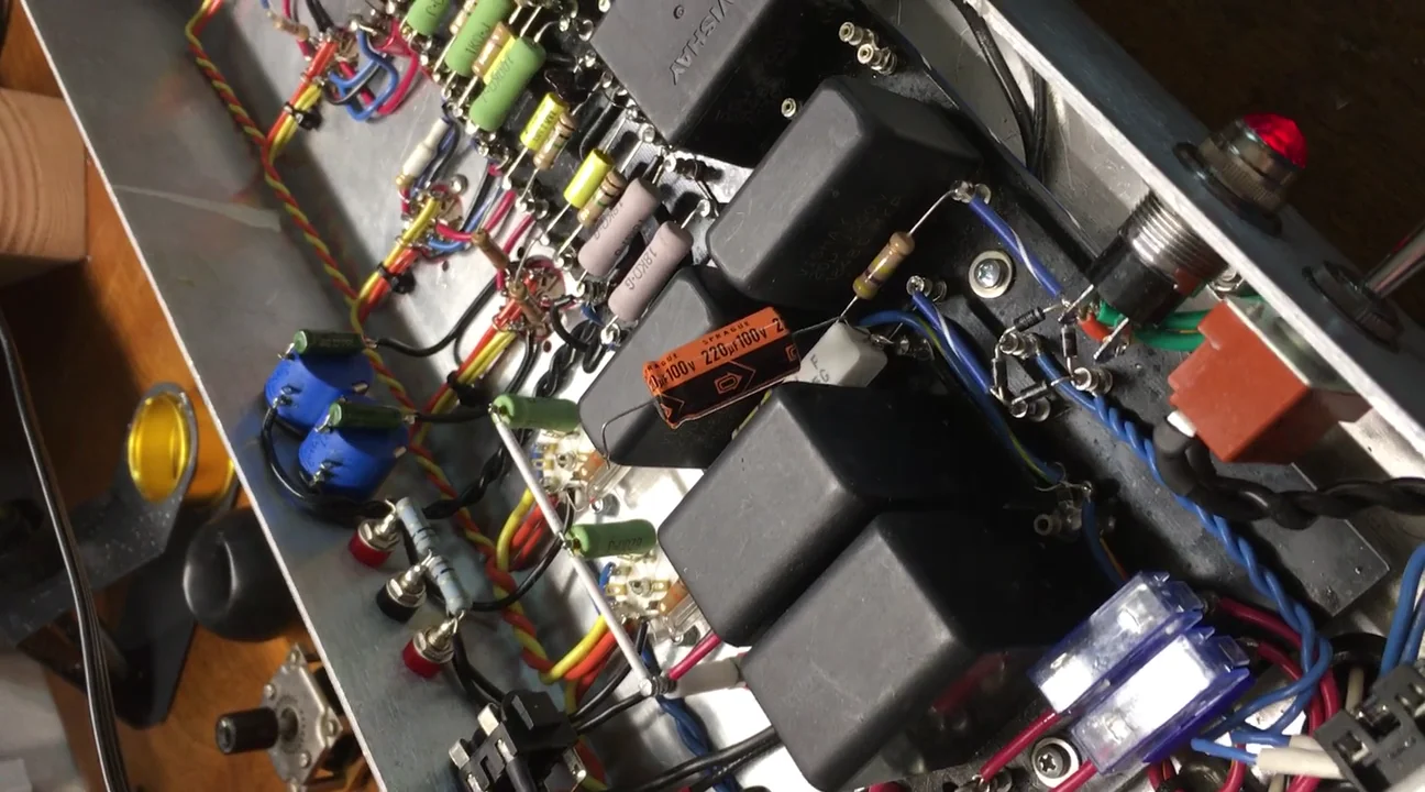
    At first I didn't even consider adding a bypass capacitor. First, I was going for the compression and "squish" that an unbypassed cathode bias provides. Plus, as I've understood that this can compound blocking distortion and crossover, whereas a resistor has instant recovery. These points may in fact be true, but after finally making my way to the cathode circuit in my troubleshooting, I added a 220µF cap across the bias resistor and it was a night and day difference. So, I underestimated this component's part of the circuit in controlling overdrive characteristics. Can you guys help me understand what might be happening? The weird part is that it is a direct coupled stage.

    I took a recorded a couple of quick video clips to illustrate. Bear in mind, this was recorded with the straight from my phone using the terrible built in mic. Also, I had a -9dB bridged T attenuator on the output so I didn't overload the phone's audio input or my piss off my neighbors(it was later in the evening). I'm going to try and capture this on my scope and try and record a better audio sample. The buzzy distortion was much more pronounced than the video indicates.

    Quick video of the unbypassed cathode:
    If I have a 50% chance of guessing the right answer, I guess wrong 80% of the time.

  • #2
    Here is a quick video of the cathode bypassed with a 220µF capacitor (It wouldn't let me put 2 video links in a single post?):

    If I have a 50% chance of guessing the right answer, I guess wrong 80% of the time.

    Comment


    • #3
      I can't honestly say I can hear much difference. I wonder what is happening at earlier stages? Without the cap you are going to need a bigger drive signal meaning that earlier stages have a larger voltage swing. You need to scope it out with a signal generator. The generator needs the send (say) 50mS bursts of 1Khz every 500mS to avoid the cap charging.
      Experience is something you get, just after you really needed it.

      Comment


      • #4
        Cathode bias with single shared bias resistor and no bypass cap:

        While the push and pull side are both working (class A mode) there is approximately no change in current through the cathode resistor. (While the push side current is increasing the pull side current is decreasing.) The cathode voltage stays approximately constant. In this case there is no local negative feedback and you get the full gain of the output stage.

        When one side of the push-pull is cut off (class B mode) the current through the cathode bias resistor is now varying. You have local negative feedback and the gain of the output stage is reduced.

        Overall you have a distorted output (even before clipping) with ‘rounded-off’ top and bottom of the wave.

        Cathode bias with single shared bias resistor, with bypass cap:

        Cathode voltage stays approximately constant throughout, there is no local feedback and you have the full gain of the output stage throughout. Although there is still a change in gain due to ‘gm doubling’ and of course the natural nonlinearity of the tubes.

        Comment


        • #5
          Originally posted by nickb View Post
          I can't honestly say I can hear much difference. I wonder what is happening at earlier stages? Without the cap you are going to need a bigger drive signal meaning that earlier stages have a larger voltage swing. You need to scope it out with a signal generator. The generator needs the send (say) 50mS bursts of 1Khz every 500mS to avoid the cap charging.
          Yeah the audio is so compressed its difficult to hear it. Hmm. So, im goin to need a burst generator? Actually, in order to capture the transient distortion component, there is no cap to charge. Should I be probing the cathode votage and grid? Or tap it at the output?
          If I have a 50% chance of guessing the right answer, I guess wrong 80% of the time.

          Comment


          • #6
            Originally posted by SoulFetish View Post
            Yeah the audio is so compressed its difficult to hear it. Hmm. So, im goin to need a burst generator? Actually, in order to capture the transient distortion component, there is no cap to charge. Should I be probing the cathode votage and grid? Or tap it at the output?

            The only reason for the burst is to watch the cap charge/ discharge and then see how it affects the waveform dynamically. It's not really a requirement but it does means you can see what the waveform looks like when the signal first starts. Trying a pair of 6L6's I need about 50% more signal in the no cap case for the same power out. That is why I suggest checking the earlier stages to eliminate that variable.
            Experience is something you get, just after you really needed it.

            Comment


            • #7
              Originally posted by SoulFetish View Post
              ... Hmm. So, im goin to need a burst generator?
              Try downloading Audacity. It's free software and it makes an amazingly flexible signal generator. It's also capable of much more if you have time/interest to explore its features.
              “If you have integrity, nothing else matters. If you don't have integrity, nothing else matters.”
              -Alan K. Simpson, U.S. Senator, Wyoming, 1979-97

              Hofstadter's Law: It always takes longer than you expect, even when you take into account Hofstadter's Law.

              https://sites.google.com/site/stringsandfrets/

              Comment


              • #8
                Originally posted by uneumann View Post
                Try downloading Audacity. It's free software and it makes an amazingly flexible signal generator. It's also capable of much more if you have time/interest to explore its features.
                It's a good tool. Just be aware of attempted side installs like toolbars etc.
                Experience is something you get, just after you really needed it.

                Comment


                • #9
                  Originally posted by Malcolm Irving View Post
                  Cathode bias with single shared bias resistor and no bypass cap:

                  While the push and pull side are both working (class A mode) there is approximately no change in current through the cathode resistor. (While the push side current is increasing the pull side current is decreasing.) The cathode voltage stays approximately constant. In this case there is no local negative feedback and you get the full gain of the output stage.

                  When one side of the push-pull is cut off (class B mode) the current through the cathode bias resistor is now varying. You have local negative feedback and the gain of the output stage is reduced.

                  Overall you have a distorted output (even before clipping) with ‘rounded-off’ top and bottom of the wave.

                  Cathode bias with single shared bias resistor, with bypass cap:

                  Cathode voltage stays approximately constant throughout, there is no local feedback and you have the full gain of the output stage throughout. Although there is still a change in gain due to ‘gm doubling’ and of course the natural nonlinearity of the tubes.
                  Whilst this is all true, the OP did specifically state that he wanted that compression effect due to the changes in gain.
                  Experience is something you get, just after you really needed it.

                  Comment


                  • #10
                    Originally posted by Malcolm Irving View Post
                    Cathode bias with single shared bias resistor and no bypass cap:

                    While the push and pull side are both working (class A mode) there is approximately no change in current through the cathode resistor. (While the push side current is increasing the pull side current is decreasing.) The cathode voltage stays approximately constant. In this case there is no local negative feedback and you get the full gain of the output stage.

                    When one side of the push-pull is cut off (class B mode) the current through the cathode bias resistor is now varying. You have local negative feedback and the gain of the output stage is reduced.

                    Overall you have a distorted output (even before clipping) with ‘rounded-off’ top and bottom of the wave.

                    Cathode bias with single shared bias resistor, with bypass cap:

                    Cathode voltage stays approximately constant throughout, there is no local feedback and you have the full gain of the output stage throughout. Although there is still a change in gain due to ‘gm doubling’ and of course the natural nonlinearity of the tubes.
                    This is my understanding as well, but the distortion artifacts I’m getting unbypassed are more extreme and sound like the result of large excursion and crossover, etc. The capacitor removes this, at least audibly. I’m wondering if maybe Nick’s suspicions are correct and the root problem is instability in an earlier stage.
                    If I have a 50% chance of guessing the right answer, I guess wrong 80% of the time.

                    Comment


                    • #11
                      Have you ever tried separate un-bypassed cathode resistors for push and pull sides? That gives reduced gain during the class A phase, as well. Overall gain of the output stage is reduced, but IMHO that can be a good thing for EL84s. EL84s are very easy to overdrive and, to my ears, get buzzy too easily compared to 6V6, 6L6, EL34 etc.

                      Edit: reduced gain also means wider input headroom, so bigger voltage swing on grid 1 is needed to reach clipping.

                      Comment


                      • #12
                        Your input signal (from the PI) is too big for the poor EL84 that overdrive too easily. The positive-going signal gets cut at some 10V, while negative-going one can easily reach -70V. So the coupling cap gets negatively charged, bias goes negative, you get crossover distortion, with some blocking distortion to boot and it sounds like that regardless of the bypass cap.

                        Try this:

                        https://www.18watt.com/storage/18-wa...z_info_311.pdf

                        (the well-known zener trick, whereby you limit the negative-going signal so the coupling caps don'g get charged)

                        Comment


                        • #13
                          Originally posted by frus View Post
                          Your input signal (from the PI) is too big for the poor EL84 that overdrive too easily. The positive-going signal gets cut at some 10V, while negative-going one can easily reach -70V. So the coupling cap gets negatively charged, bias goes negative, you get crossover distortion, with some blocking distortion to boot and it sounds like that regardless of the bypass cap.

                          Try this:

                          https://www.18watt.com/storage/18-wa...z_info_311.pdf

                          (the well-known zener trick, whereby you limit the negative-going signal so the coupling caps don'g get charged)
                          This is most definitely not what is happening.
                          If I have a 50% chance of guessing the right answer, I guess wrong 80% of the time.

                          Comment


                          • #14
                            Originally posted by Malcolm Irving View Post
                            Have you ever tried separate un-bypassed cathode resistors for push and pull sides? That gives reduced gain during the class A phase, as well. Overall gain of the output stage is reduced, but IMHO that can be a good thing for EL84s. EL84s are very easy to overdrive and, to my ears, get buzzy too easily compared to 6V6, 6L6, EL34 etc.

                            Edit: reduced gain also means wider input headroom, so bigger voltage swing on grid 1 is needed to reach clipping
                            I was thinking about this earlier and wondering if this may be a better approach. Im glad you mentioned it. Im wondering if the sudden excursion caused by 1 tube going into cutoff during the class B portion of the waveform is causing some of the
                            problems im hearing. I have alot flexibility with this driving/biasing design. Right now, with a plate voltage of 319V, i have the cathodes biased at about +7.5V through a shared 100R resistor, and the grids at around -4V. (Technically, it is a fixed bias, but its a hybrid to take advantage of the sonic effects of cathode biasing). But i can adjust it anywhere in the fixed to cathode bias range. I have 51K grid stoppers on the EL84 to clamp the peak input signal, but I can bring that value down to
                            A few hundreds of ohms if i want to drive them positive. But I would need to remove the EL84 cathode resistors. You can’t use operate in AB2 using cathode biasing.
                            If I have a 50% chance of guessing the right answer, I guess wrong 80% of the time.

                            Comment


                            • #15
                              I had the same problem.
                              I had the center tap of my filament winding grounded at the output tube cathodes.
                              The excursions there were feeding back into the preamp at higher gains.
                              Elevating the reference with a bypassed voltage divider (70v or so) took care of the issue for me.
                              YMMV, of course!

                              Comment

                              Working...
                              X