 Tweet
Tweet
This week I�ve been going thru the Ampeg SVT VR amps in our inventory, having found some that havn�t been serviced since 2011 and 2013, though most had been gone thru 3 or 4 years ago.
I had been putting off the task of fabricating a proper power tube service plate made from a clear plastic, allowing you to actually see where the measurement probes are in trying to clip across the plate resistors during tube matching. I had made a simple one out of a fiber report cover, having used the metal cover plate as the template for the power tube socket holes & preamp/driver tube holes. Then, did my best to located the additional holes for the plate resistors.
While that was far better than putting an insulating �blanket� under the PCB so nothing shorted to the board, it was still dangerous fishing in the dark trying to clip onto the power resistor leads while trying not to burn your fingers using that report cover service plate.
So, I looked at what McMaster-Carr had in Clear Plastics and ended up buying one 12� x 12� sheet each of Clear Acryic, Clear Polycarbonate & Clear high strength Acrylic, with temperature ratings in the 160 to 180 deg F.
After using the metal cover plate as a template, to cut to size and then mark the hole locations on the protective film over the plastic, I then located the hole centers using calipers and adjustable machinist squares. I clamped the two sheets together with some Kant-Twist clamps until I had all the cover plate holes located and center-punched.
I have a set of really fine machined hole saws that form precision cuts and I cut the 1-1/4� and 1� dia holes for the tubes, and used a deep-thoat Whitney Punch to punch the mounting holes for the plate & tube sockets.
Then, with the film still in place, I mounted the new plastic cover plate to the power tube PCB, and one resistor at a time, located the plate resistor leads� X-Y positions and center-punched those. I also located the Screen resistor holes, as well as the centers for the 7-pin I/O connector as well as the screen supply and two holes for the O/T HV connections. I punched those holes with the Whitney Punch, using 5/16� for the plate resistors and 1/4� for the screen resistors.
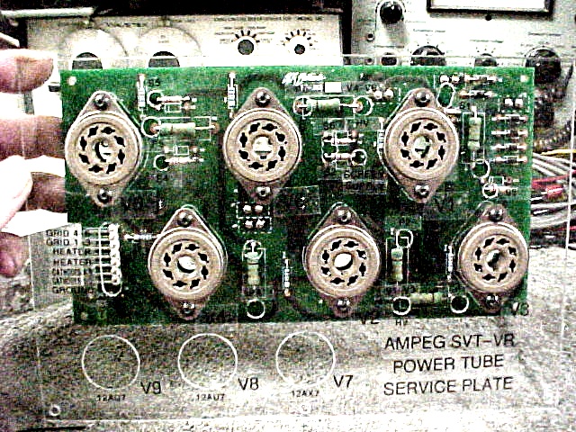
After I deburred everything, I finally peeled away the protective film, exposing the new shiny Acrylic Service Plate, and mounted it to the Power Tube PCB. I then added P-Touch labels to identify everything.


This is what I had been using...the brown fiber report-cover service plate to mount the power tube PCB onto. Still dangerous probing in the dark trying to find the resistor leads.


Sure made life easier being able to see just where the long EZ-Hook probes are as you�re poking them into the high voltage area with the amp powered up. I still am more comfortable checking and matching these KT-88 or 6550 power tubes on the SVT-CL chassis, where you�re only sitting under half a volt DC.


I had been putting off the task of fabricating a proper power tube service plate made from a clear plastic, allowing you to actually see where the measurement probes are in trying to clip across the plate resistors during tube matching. I had made a simple one out of a fiber report cover, having used the metal cover plate as the template for the power tube socket holes & preamp/driver tube holes. Then, did my best to located the additional holes for the plate resistors.
While that was far better than putting an insulating �blanket� under the PCB so nothing shorted to the board, it was still dangerous fishing in the dark trying to clip onto the power resistor leads while trying not to burn your fingers using that report cover service plate.
So, I looked at what McMaster-Carr had in Clear Plastics and ended up buying one 12� x 12� sheet each of Clear Acryic, Clear Polycarbonate & Clear high strength Acrylic, with temperature ratings in the 160 to 180 deg F.
After using the metal cover plate as a template, to cut to size and then mark the hole locations on the protective film over the plastic, I then located the hole centers using calipers and adjustable machinist squares. I clamped the two sheets together with some Kant-Twist clamps until I had all the cover plate holes located and center-punched.
I have a set of really fine machined hole saws that form precision cuts and I cut the 1-1/4� and 1� dia holes for the tubes, and used a deep-thoat Whitney Punch to punch the mounting holes for the plate & tube sockets.
Then, with the film still in place, I mounted the new plastic cover plate to the power tube PCB, and one resistor at a time, located the plate resistor leads� X-Y positions and center-punched those. I also located the Screen resistor holes, as well as the centers for the 7-pin I/O connector as well as the screen supply and two holes for the O/T HV connections. I punched those holes with the Whitney Punch, using 5/16� for the plate resistors and 1/4� for the screen resistors.
After I deburred everything, I finally peeled away the protective film, exposing the new shiny Acrylic Service Plate, and mounted it to the Power Tube PCB. I then added P-Touch labels to identify everything.
This is what I had been using...the brown fiber report-cover service plate to mount the power tube PCB onto. Still dangerous probing in the dark trying to find the resistor leads.
Sure made life easier being able to see just where the long EZ-Hook probes are as you�re poking them into the high voltage area with the amp powered up. I still am more comfortable checking and matching these KT-88 or 6550 power tubes on the SVT-CL chassis, where you�re only sitting under half a volt DC.
Comment